CAS
MICROBLOCK
Interpretation
of
Box
Doto
left
Edge
Ch
r
Print Positions Right
a
Edge
1 2 3 4 5 6 7 8 9
10
11
12
Char
Meaning
of
left
Edge
Character
P
P P
P
A T T
T T
V V
V
A
A
A
P
-+
P
P
B
N N N N
B C C
-+
D C C
C C
D
E E E
E
D
F F
F F
D
A A A
A
L
H H H
H
S
L L L
L
f-c
f-F
F
F F
C G G
G G
C
E E E
E
C D D
D D
J
J J J
R
K
K
K K
100111---0227
A
QltO
A-D
B ItO
B
__
F
D
Q23.R
L RG'E2+S, T
S MS-REQ'
D-3
C
RESET
C 1+1C(21-22)
R E
(02-07).ROA
R
EXCEP
I
Q6-OOO000-
OF
Figure 2
P P P P
U U U U
Q
A A
P P
E
N
M
M M
D D
C C C C
E E
G
F F
F
F
A
H H H H
L L
L
L
F F F F
G G G G
E
E
D D
D D
J
K
J J J
P
P P
U
QQ
Q
Q
C
C
C
M M
M M
R
R
R
R
C C C C
G G G
C-
F F
B
B
B B
L L L L
F F
F F
G
G G G
D D
J
J J J
A Parallel Adder Inputs
A Parallel Adder
Output
Destination
(5)
Serial Adder Inputs
Serial Adder
Output
Destination
(s)
D Misc.lngoting Controls
local
Store Control
Mark Setting and Storage
Requests
C Mise.Controls
R Branching
Figure 1
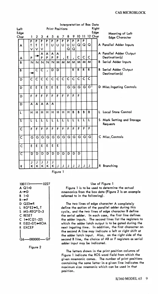
Use
of
Figure I
Figure I is to be used to determine
the
actual
mnemonics
from
the box
data
(Figure 2 is an example
referred to in
the
following).
The two lines
of
edge
character
A complete Iy
define
the
action
of
the parallel odder during this
cycle,
and
the
two lines of edge
character
B
define
the
serial
adder.
In
each
easel
the first line defines
the
adder
inputs. The second lines list
the
registers to
which the
odder
latch
output
is
to be
gated
during
the
next ingating time.
In
addition,
the
first
character
on
the
second A line may
indicate
a left or right shift
at
the adder
latch
input. Also, on the right side
of
the
second B
line,
the
choice
of
AB
or F registers as seriol
odder input
may
be
indicated.
The
letters shown
in
the
print
position columns
of
Figure 1
indicate
the
ROS
word field
from
which
the
given
mnemonic comes. The number of print positions
containing
the some
letter
in a given line indicates the
maximum
size
:nnemonic which
can
be used in
that
position.
S/360
MODEL
65