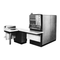
2365 FAILURE ANALYSIS TECHNIQUES
The following items provide a checklist for investigating 2365 problems.
1.
Check the 18.0v power supply (PS 16).
It
must
be set for 19.Ov for proper sense
amp response.
2. Check the array temperature for 95 ± 2
o
r.
Use
thermometer
PN
5392366.
NOTE: Some
intermittents
have been c:wsed
by
this temperature cycling. This
may be checked
by
making
five
or
six readings at 3-mir.ute intervals.
3. Check all power supply voltages
at
the test jacks (see installation manual for
compensated test
jack
voltages).
Ifthe
trouble persists after one pass through this
list, testing the voltages on the back-panel pins is recommended.
4.
Run
a
two
point
shmoo
plot. With the Z-voltage setting at nominal, raise the XY
drive voltage
to
failure, and lower
it
to
failure. Compare these failures with the
previous
shmoo
plot.
5.
Scope the X
and
Y drivers and gates.
The
proper
waveshapes are shown in the 2365
maintenance manual.
Stop
machine. Scope all driver
outputs
(X
and
Y) for down level. Maximum
acceptable down level is less
than
2vdc. MM-ALD reference pages may be used for
scope
paints.
If
the down level
of
a driver
output
is +2v
or
greater, the driver card
should be replaced.
If
the
problem
still exists, systematically remove the matrix switch
cards one at a time. Check driver
off
level after each switch is removed. When level
falls below 2v, that removed switch
is
defective.
The
32
driver
outputs
can be observed
on any
matrix
switch input.
6. Using the probe
adapter
tool and the
453
scope with a 22o..ohm
(approximate)
buffer
resistor
(to
slow down
the
preamplifier
input
and
smooth
out
some
of
the noise),
perform
the following checks: (See Maintenance manual for setup.)
a.
Scope the suspected core signal. Compare
it
with
other
output
signals.
b. Check
the
output
signal for proper relationship
to
the strobe pUlse.
NOTE: A late noise
and
a late strobe or an early noise
and
an early strobe can
result in picked bits. Also, a late peaking core with a late strobe can result in
dropping bits.
c. Check for the following grouping
of
the strobe pulses:
(I)
Group I to
2:
about
IOns.
(2)
Group
2
to
3:
about
IOns
to
15ns.
(3)
Group
3
to
4:
about
IOns
to
15ns.
7.
Check for
the
matrix
switch bias current:
X bias to A2N6B2; then to A2L6B2.
Y
bias to
AIN6B2;
then to
AIL6B2.
NOTE: The slip-on
connector
has been
found
loose several times. A parallel-wire EC
is
in process.
8. With tweezers, gently pull the blue and white wire on
the
array
at
the
suspected
locations. The wire
should
come
off
if
the weld is defective. Do
not
pull with the
fmgers;
you
may
induce more failures than
you
find.
68
S/360
MODEL 65

 Loading...


