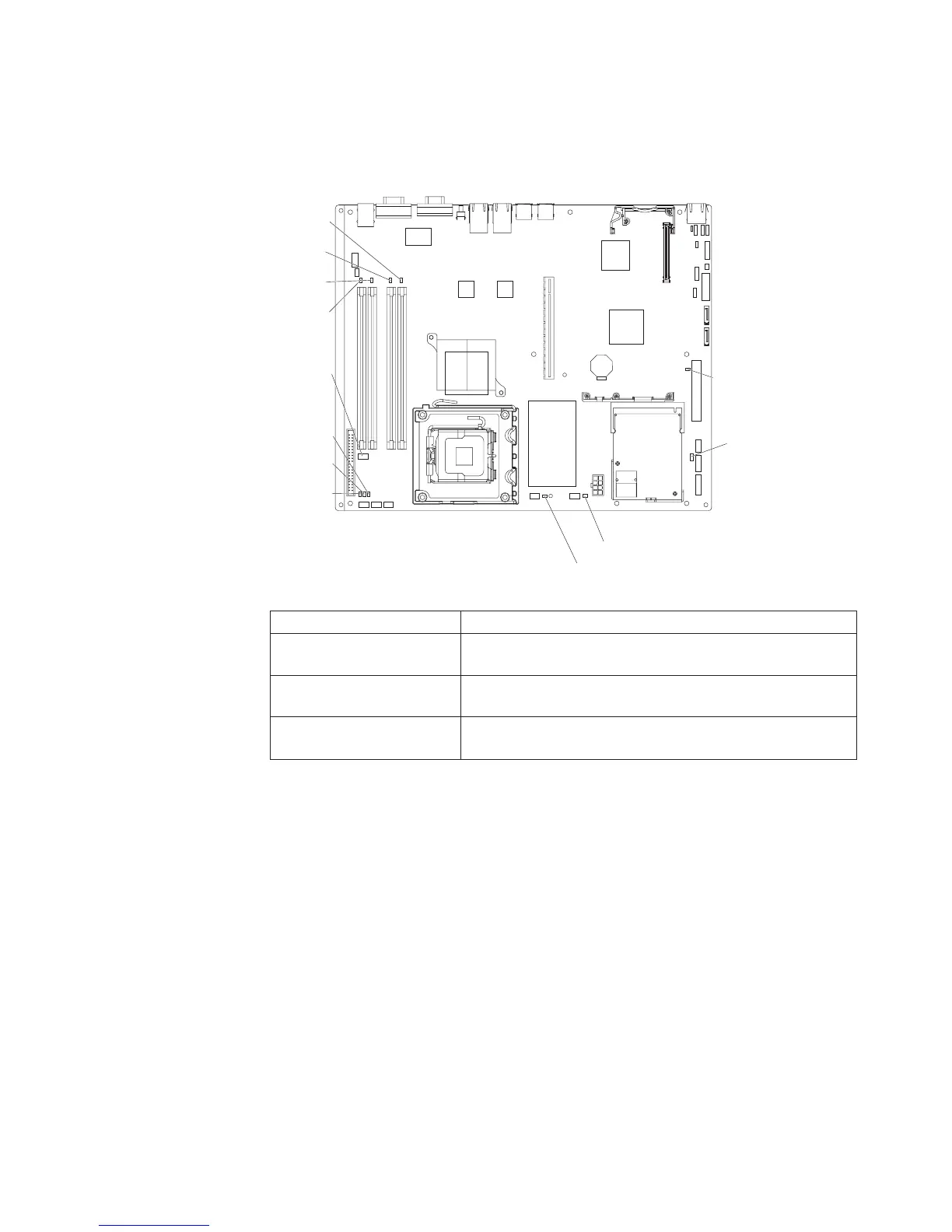
EasyManuals Logo

IBM System x3250 User Manual

IBM System x3250
74 pages
To Next Page IconTo Next Page
To Previous Page IconTo Previous Page
Page #29 background imageLoading...
Page #29 background image
System-board LEDs
The following illustration shows the light-emitting diodes (LEDs) on the system
board.
Voltage
regulator
error LED
Standby
power
LED
DIMM 4
error LED
DIMM 3
error LED
DIMM 2
error LED
DIMM 1
error LED
Fan 3
error LED
Fan 4 error LED
Fan 2
error LED
Fan 5 error LED
Fan 1
error LED
Baseboard
management
controller
heartbeat
LED
Table 3. System-board LEDs
LED Description
Error LEDs When one of these LEDs is lit, it indicates that the associated
component has failed.
Baseboard management
controller heartbeat LED
This LED flashes to indicate that the mini-BMC is functioning
normally.
Standby power LED When this LED is lit, it indicates that the server is connected
to ac power.
Chapter 2. Installing optional devices 15

Table of Contents

Other manuals for IBM System x3250

Questions and Answers:

Question and Answer IconNeed help?

Do you have a question about the IBM System x3250 and is the answer not in the manual?

IBM System x3250 Specifications

General IconGeneral
Processor Sockets1
Memory Slots4
ProcessorIntel Core 2 Duo
StorageSATA
Maximum Internal StorageUp to 4TB
Hard Drive InterfaceSATA
RAID SupportRAID 0, 1
NetworkGigabit Ethernet
Operating System SupportWindows Server, Linux

Related product manuals