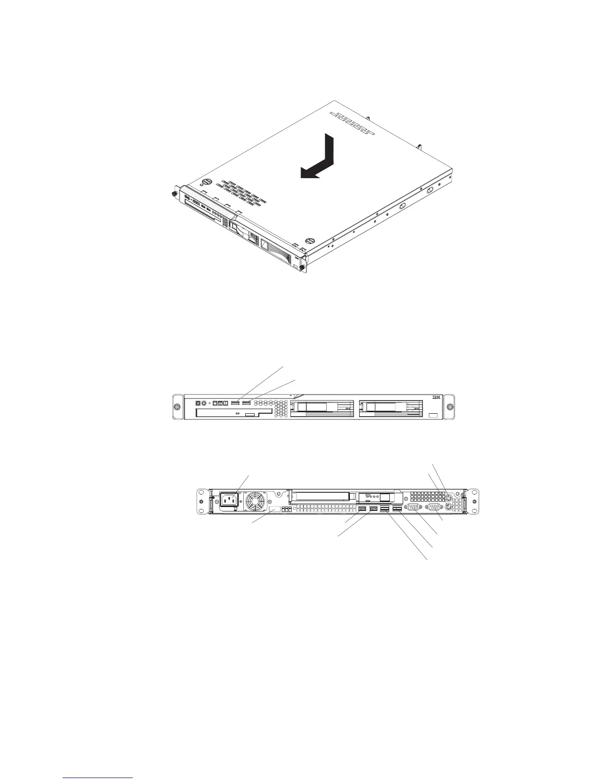
Installing the cover
To install the cover, place it into position and slide it forward.
Connecting the cables
The following illustrations show the locations of the input and output connectors on
the front and rear of the server.
Front
USB 1 connector
USB 2 connector
Rear
Power-cord connector
Mouse connector
Keyboard connector
Serial connector
Video connector
Ethernet 2 connector
Ethernet 1 connector
USB 3 connector
USB 4 connector
Systems-management
connector
You must turn off the server before you connect or disconnect cables.
See the documentation that comes with any external devices for additional cabling
instructions. It might be easier for you to route cables before you connect the
devices to the server.
Cable identifiers are printed on the cables that come with the server and devices.
Use these identifiers to connect the cables to the correct connectors.
If the server comes with an installed operating system, see the documentation that
comes with the operating system for additional cabling instructions.
Chapter 2. Installing optional devices 33