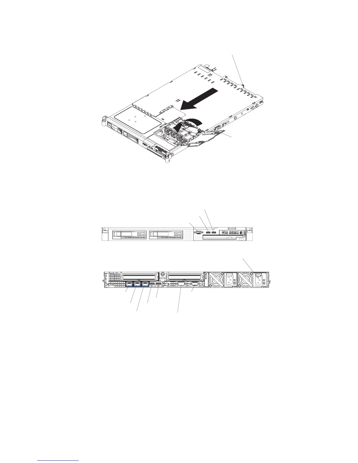
v Tighten the thumbscrew at the back of the server.
Thumbscrew
Fan door
Connecting the cables
The following illustrations show the locations of the input and output connectors on
the front and rear of the server.
Video connector
USB 4 connector
USB 3 connector
Video
connector
Serial
connector
USB 1
USB 2
Ethernet 1
Ethernet 2
Systems-
management
Ethernet connector
Power-supply
connector
You must turn off the server before you connect or disconnect cables.
See the documentation that comes with any external devices for additional cabling
instructions. It might be easier for you to route cables before you connect the
devices to the server.
Cable identifiers are printed on the cables that come with the server and optional
devices. Use these identifiers to connect the cables to the correct connectors.
Figure 2. Front of server
Figure
3. Rear of server
Chapter 2. Installing options 27
 Loading...