19
1. INSTALLATION
Protective measures
Before starting any installation work, it is essential to disconnect the power supply.
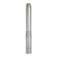
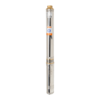
Protection must be provided against accidental power restoration. 3ti, 3t2i, 3Stm
3SDm, 3,5”SRH, 4SD and 4SDm, 4ISP, 4ISPm, 6ISP, 6SD pumps can be supplied in two
parts due to their dimensions. One is the hydraulic part of the pump, the other is the
electric motor. Before assembling the two parts into one unit, unscrew the screws
securing the cable protection strip. Then unscrew the screws securing the mesh lter
and remove it. Unscrew and remove the mounting nuts and washers from the engine.
Once the motor has been positioned vertically, place the hydraulic part on top of it
so that the multi-spline shaft ending of the motor is placed in the pump coupling. If
during assembly there are diculties with coupling, the motor shaft must be turned
so that the shaft splines are aligned with the motor coupling. When the hydraulic part
is correctly seated on the motor, it should rest completely on the motor’s top bearing
body. Thus prepared, the unit can be screwed together using nuts and washers. Nuts
must be screwed “crosswise”. The minimum torque required to tighten the nuts for
4” motors is 18 Nm.
Pump installation
Tightening the nuts imprecisely can cause them to loosen during operation and “sink”
the motor in the borehole. Once the hydraulic part has been assembled on the motor
and the power cable routed on the pump, the mesh filter and then the cable protec-
tion strip must be tted and bolted in place. Lowering the pump into the borehole
without a safety strip can damage the cable insulation, which can result in pump
malfunction or electrocution of the operator.
Some pumps are equipped with a oat-controller that automatically switches the
pump on and o depending on the water level.
As the water level rises, the oat, which is empty inside, goes upwards with the water
table. When the switch-on level is reached, the ball inside the oat drops, connecting
the electrical contacts so that the pump motor starts. As the water is pumped out,
the water table can drop and the oat goes down with it. When the switch-o level
is reached, a falling ball inside the oat disconnects the contacts thereby switching
o the pump motor. The on and o level can be adjusted by the user by changing
the length of the cable between the oat mount and the oat. If the capacity of the
well is high enough that the mirror will not drop, the user must remember that the
pump will operate as long as the oat oats above the pump.
The minimum cable length between the oat mount and the oat must not be less