21
1. INSTALLATION
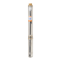
Pump installation
m
3
/h 2 4 5 7
10
15 20 25 30 40
mm 102 103 115 160 195 240 285 320 350 410
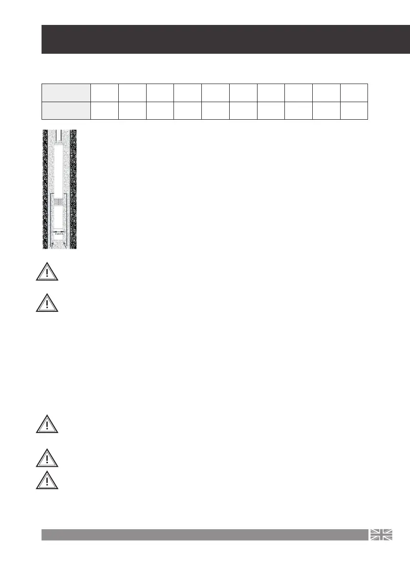
Operating the pump in a well with a larger diameter than that shown in the
table can lead to motor overheating and malfunction. In case the well where
the pump is to operate has a diameter larger than that indicated in the table,
the pump must be installed in a special casing to ensure proper cooling. The
g. illustrates schematically the idea of such a casing.
The pump must be installed above the filtration section of the well. The mini-
mum distance between the upper edge of the last part of the well filter and the
lower edge of the engine must not be less than 30 cm. Operating the pump
installed closer to the bottom can cause sand to be sucked up, and this can
lead to faster wear of the pumping components. Setting the pump in silt will
lead to overheating of the motor.
Table for pumps up to 98 mm diameter:
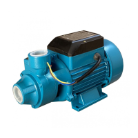
The IBQ series pumps absolutely need to function properly work with a tank with
a minimum capacity of 100L. The pumps can only work with mechanical switches
of the PC-SK2 and LCI types. PUMPS CANNOT OPERATE WITH INVERTERS
.
The pump cannot run “dry” without water. Dry operation will result in damage to the unit,
in which case repair will only be possible against payment.
To prevent possible dry running, the pump should be installed at such a depth that the
lowest dynamic water level (water level determined during uninterrupted pumping at
slow outow) is at least 2 m above the pump’s discharge port.
If the capacity of the well makes such an installation impossible (the well is too inecient
in relation to the capacity of the pump), choose accordingly to:
• install a permanent ow restriction valve on the discharge pipe,
• install a dry-running protection device that monitors the water level and cuts o
the power supply to the unit in the event of danger of dry running.
When lowering the pump into the well, ensure that the pump power supply cable is
attached to the discharge pipe with plastic ties every 2 meters or less. In case the pump
is installed at great depths, the cable not attached to the discharge pipe may break under
its own weight.
Is advisable to also suspend the pump on a steel cable so that the pump unit does not
drown in the well in the event of a spontaneous uncoupling of the discharge pipe.
A non-return valve should be installed directly above the pump to protect the unit from
the impact of returning water.