31
13 Reach through the adaptor and remove the
coupling parts.
14 Check both the coupling halves for chipping
and wear and do not hesitate to replace
them.
15 Install the bottom bearing into its brass hou-
sing paying attention to have thewhite plastic
ring facing up.
16 Install the upper bearing into the ice breaker
starting by the radial portion that must be fit-
ted with the flat surface facing up.
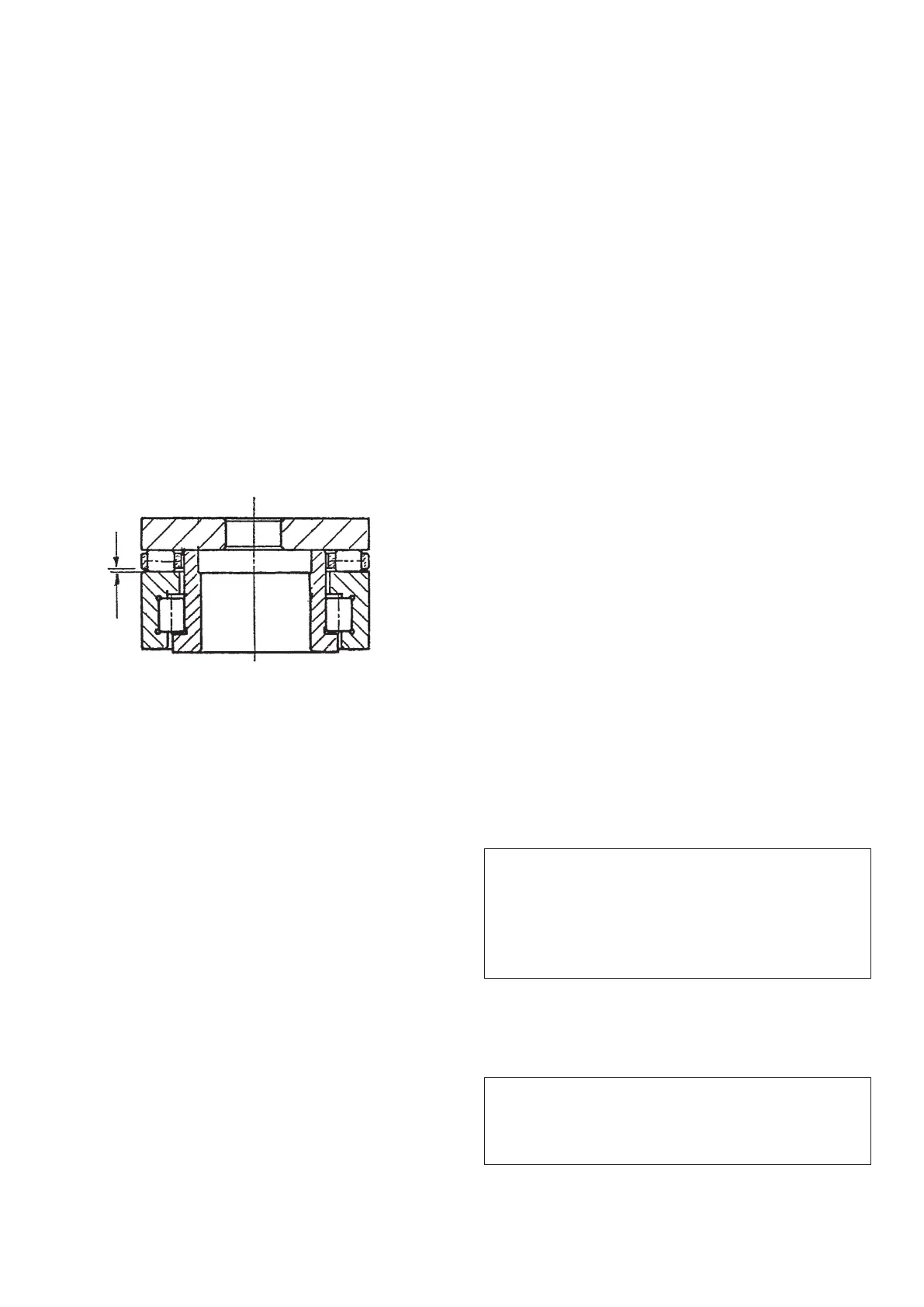
17 Apply some lubricant (grease) on the upper
surface then install the rollers cage with the
smaller openings of the same facing up so to
leave a small gap between plastic cage and
flat surface of the botton portion of the bea-
ring (see drawing).
18 Apply some move lubricant then place the
S.S. trust washer.
19 After to have replace the O ring into the ice
breaker fit the same on top of the auger and
secure it with the top bolt.
20 Install the auger/icebreaker into the evapora-
tor followingthepreviousstepsinreverse.
D REPLACEMENT OF THE GEAR MOTOR
ASSY
1 On F120-F200,SF300 and SF500 remove the
front/top and side/rear panels and on
SFN1000 remove the front, rear, top and left
side panels.
2 Remove the three/four bolts and washers
securing the gear reducer base to the unit-
chassis, then remove bolts and lock washer-
swhich attach the bottom of the aluminium
adaptor to the gear reducer case cover.
3 Follow the steps of item E to remove the gear
motor magnetic sensor.
4 Trace and disconnect the electric wires
leads of the drive motor. Lift and remove the
entire gear motor assembly.
5 To install the replacement gear motor assy
follow the above steps in reverse.
E REPLACEMENT OF THE FREEZING
CYLINDER
1 Follow the steps at item H to remove the ice
spout.
2 Remove the clamp fastening the water hose
to the water inlet port of the freezer assy.
Place a water pan under this water inlet port
then disconnect the water hose and collect
all water flowing from freezer and from water
hose.
3 With draw the evaporator sensor probe from
the its holder as stated in item B.
4 Recover the refrigerant from the system and
transfer it in a container so to reclaim or recy-
cle it.
5 Unsolder and disconnect the capillary tube
and the accumulator/suction line assy from
the outlet line of the freezing cylinder.
6 Remove the three/four bolts and washers
securing the gear reducer base to the unit
chassis, then remove bolts and lockwashers
which attach the bottom of the aluminium
adaptor to the gear reducer case cover.
7 Lift the freezer up and off the gear motor
assembly, then if necessary remove the alu-
minium adaptor by removing the three moun-
ting screws and lockwashers.
8 To install the replacement evaporator follow
the above steps in reverse.
NOTE. It is imperative to installa replace-
ment drier whenever the sealed refrigeration
system is open.
Do not replace the drier until all other repairs
or replacements have been completed.
NOTE. Thoroughly evacuate the system to
remove moisture and non condensables
after evaporator replacement.