3
Vertical mounting of the ICM2813 in the previous circuit board
location
1. Place the ICM mounting plate over the previous circuit board
location with arrow facing up as seen in Figure .
2. Move the ICM mounting plate over to the right ” for fresh
metal to drill through and mount the unit too.
3. Hold in place with your hand or use tape to secure.
4. With a pencil or marker, mark the () holes labeled “Drill
” Hole” as seen in Figure .
5. Remove ICM mounting plate and drill () holes with a ”
drill bit.
6. Line up the (ICM2813 with
the () holes shown on the ICM mounting plate. These two
components only connect one way.
each one snaps into the ICM mounting plate.
8. With the ICM2813
plate, line up the ()
holes drilled in Step
above.
press each of the ()
snaps and locks into
the sheet metal surface.
Check to make sure all
(
fastened to the sheet metal.
Drill
3/16”
Hole
Drill
3/16”
Hole
Drill
3/16”
Hole
Drill
3/16”
Hole
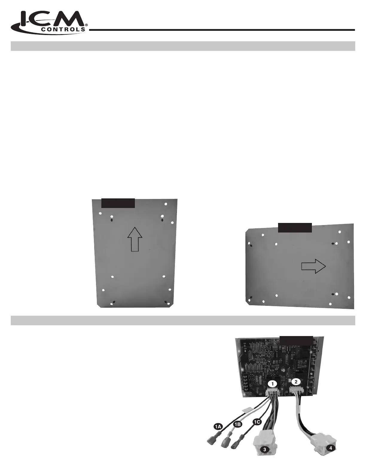
Figure 1
Horizontal or Vertical mounting of the ICM2813 in a new
location
1. Select desired location for the ICM mounting plate.
2. Select orientation (horizontal down flow or vertical up flow)
for the ICM mounting plate.
3. Hold in place with your hand or use tape to secure.
4. With a pencil or marker, mark the () holes labeled “Drill
” Hole” as seen in Figure .
5. Remove ICM mounting plate and drill () holes with a ”
drill bit.
6. Line up the (ICM2813 with
the () holes shown on the ICM mounting plate. These two
components only connect one way.
each one snaps into the ICM mounting plate.
8. With the ICM2813
plate, line up the (
Step above.
each one snaps and locks into the sheet metal surface. Check
to make sure
all (
are securely
fastened to the
sheet metal.
Drill
3/16”
Hole
Drill
3/16”
Hole
Drill
3/16”
Hole
Drill
3/16”
Hole
Figure 2
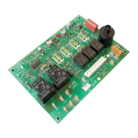
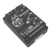
1. Plug -pin wiring harness supplied with the ICM2813 board into
the pin socket on the ICM2813 board as seen in Figure location
. It is a keyed connector and only connects one way. There are
wires which have ¼ “quick connects attached to the ends as seen
in Figure labeled . Connect these wires as stated below:
= Blue wire connects to transformer secondary side or
inline fuse if used.
= Green wire: Connects to Earth Ground
2. Plug the -pin wiring harness into the ICM2813 as seen in Figure
location . It only connects one way.
3. Connect the opposite ends of both harnesses labeled & on
Figure to the mating connections of the harnesses on the furnace.
4. Ensure all other connections are wired per wiring diagram.
Figure 3
MOUNTING THE ICM2813
WIRE HARNESS CONNECTIONS