5
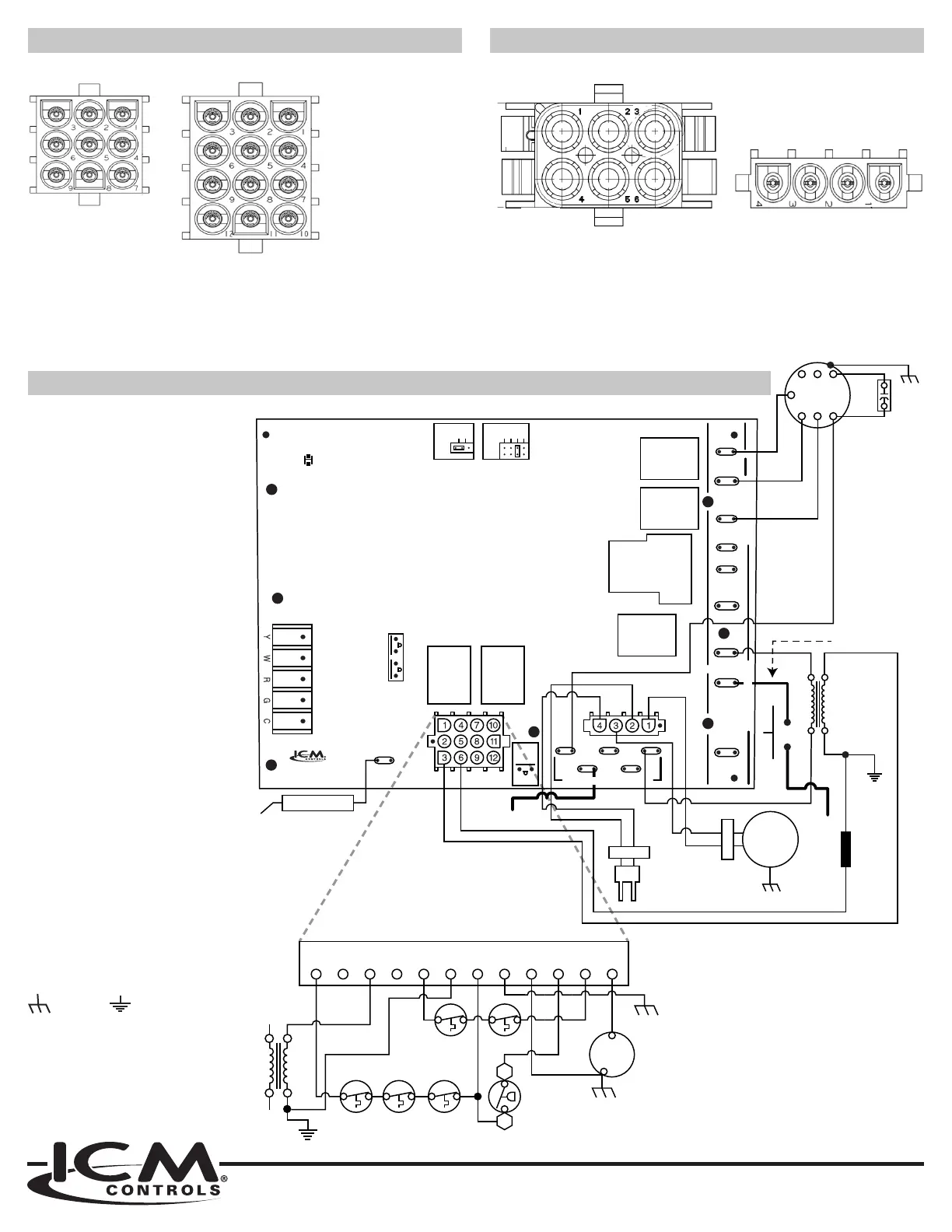
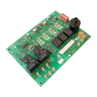
WIRING DIAGRAM
WIRING HARNESS 9 TO 12 PIN WIRING HARNESS 4 TO 6 PIN
T1
T3
T2
T4
T5
HEAT OFF
DELAY
60
90
120
180
COOL OFF
DELAY
45
2
LED1
HUM
XFRM
LINE
EAC
HEAT
PARK
FAN
COOL
PARK
120 VOLT HOT
FS
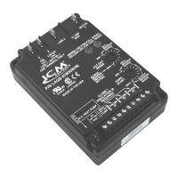
ICM2813
24V
ONLY
HUM
L2
120
VAC
L1
NEUTRAL
LINE
INDUCED
DRAFT
MOTOR
NEUTRAL
*See 1A under
Wire Harness
Connections
See NOTE in Install
section on page 2.
LINE
24V SEC
PRI
GND
HSI
BLOWER
MOTOR
BRN
BRN
CAP-1
Cool Speed
Heat Speed
Continuous Fan
Flame Sensor
P1 P2
Neutral
PIN 11
PIN 10
PIN 9
PIN 7 PIN 8
PIN 5 PIN 6
PIN 3 PIN 4
PIN 1 PIN 2
24V SEC
GND
121110987654321
PRS
NOC
RS 1
Chassis
GND
GAS
VALVE
LS
Primary
RS 2
LS 2 LS 2
120 VOLT NEUTRALS
INLINE FUSE*
120 VOLT HOT
DOOR SWITCH
800.365.5525
www.icmcontrols.com
P1 Plug Pin Out
= High limit output
= N/A
= VAC
= N/A
= Rollout switch 1
= VAC common
= High limit input
= Ground
= Main Valve common
= Pressure switch
= Rollout switch
= Main valve
P2 Plug Pin Out
= Inducer blower
= Hot surface ignitor
= Neutral
4 = Neutral
Legend
EAC = Electronic air cleaner
FS = Flame sensor
GND = Ground
HSI = Hot surface ignitor
LS = Limit switch
PRI = Primary
PRS = Pressure switch
RS = Rollout switch
SEC = Secondary
XFRM = Transformer
(Limit Switch In)
Connected to Pin
(Rollout Switch)
(Gas valve)
(Pressure Switch)
(Limit Switch Out)
(Rollout Switch)
Earth Ground)
Hot Surface Ignitor
Neutral
Inducer Blower
Neutral
(Limit Switch Out)
input
(Rollout Switch)
Earth Ground)
(Limit Switch In)
Earth Ground
Earth Ground)
(Pressure Switch)
(Rollout Switch)
(Gas valve)
Inducer Blower
Hot Surface Ignitor
Neutral
Neutral
Chassis
ground
Earth
ground
P1 Harness (9-Pin End) P2 Harness (6-Pin End)P1 Harness (12-Pin End) P2 Harness (4-Pin End)