EasyManua.ls Logo

ICM Controls MP2010L - User Manual

ICM Controls MP2010L
2 pages
Print Icon
To Next Page IconTo Next Page
Loading...
Important Safety Information
WARNING!
:
Always turn off power at the main power supply before installing, cleaning,
or removing thermostat.
•Thisthermostatisfor24VACapplicationsonly;donotuseonvoltagesover30VAC
•Donotshortacrossterminalsofgasvalveorsystemcontroltotestoperation;thiswilldamageyour
thermostatandvoidyourwarranty
•Allwiringmustconformtolocalandnationalelectricalandbuildingcodes
•Donotuseairconditioningwhentheoutdoortemperatureisbelow50degrees;thiscandamage
yourA/Csystemandcausepersonalinjuries
•Usethisthermostatonlyasdescribedinthismanual
Specifications
Electrical rating:
•24VAC(18-30VAC)
•3.0VDC(2“AAA”batteries)
•1ampmaximumperterminal
•3ampmaximumtotalload
Temperature control range: 45°Fto90°F(7°Cto32°C)Accuracy:±1°F(±0.5°C)
System congurations:1-stageheat,1-stagecool,heatpump,gas,oil,electric
Timing:
Anti-shortCycle:
4minutes
Backlight Operation:5seconds(congurableONorOFF)
Terminations:G,B,O,Y,RH,RC,W,C
Package Contents/Tools Required
Package includes:MP2010Lthermostatonbase,thermostatcover,wiringlabels,screwsandwall
anchors,2“AAA”batteries,Installation,OperationandApplicationGuide
Tools required for installation:Drillwith3/16”bit,hammer,screwdriver
ELECTRICAL SHOCK HAZARD
– Turn off power at the main service panel by removing
the fuse or switching the appropriate circuit breaker to the OFF position before
removing the existing thermostat.
1. Turnoffpowertotheheatingandcoolingsystembyremovingthefuseorswitchingtheappropriate
circuitbreakeroff.
2. Removecoverofoldthermostat.Thisshouldexposethewires.
3. Labeltheexistingwireswiththeenclosedwirelabelsbeforeremovingwires.
4. Afterlabelingwires,removewiresfromwireterminals.
5. Removeexistingthermostatbasefromwall.
6. Refertothefollowingsectionforinstructionsonhowtoinstallthisthermostat.
To Remove Existing Thermostat
Parts Diagram
Downbutton
Upbutton
RC/RHJumper
Leftswitch
Resetswitch
Gas/Elec
Battery
compartment
High
Temperature
Protection
Freeze
Protection
Modeswitch
Fanswitch
HP/Non-Heat
Jumper
Rightswitch
To Install Thermostat
ELECTRICAL SHOCK HAZARD
– Turn off power at the main service panel by removing
the fuse or switching the appropriate circuit breaker to the OFF position before
removing the existing thermostat.
IMPORTANT: Thermostat installation must conform to local and national building and
electrical codes and ordinances.
Note:Mount the thermostat about ve feet above the oor. Do not mount the thermostat on an
outside wall, in direct sunlight, behind a door, or in an area affected by a vent or duct.
1. Turnoffpowertotheheatingandcoolingsystembyremovingthefuseorswitchingthe
appropriatecircuitbreakeroff.
2. Toremovecover,pullgentlyattheseamatthetop.
3. Putthermostatbaseagainstthewallwhereyouplantomountit(Besurewireswillfeedthrough
thewireopeninginthebaseofthethermostat).
4. Marktheplacementofthemountingholes.
5. Setthermostatbaseandcoverawayfromworkingarea.
6. Usinga3/16”drillbit,drillholesintheplacesyouhavemarkedformounting.
7. Useahammertotapsuppliedanchorsinmountingholes.
8. Alignthermostatbasewithmountingholesandfeedthecontrolwiresthroughslitinthermal
intrusionbarrierandintowireopening.
9. Usesuppliedscrewstomountthermostatbasetowall.
10.Insertstripped,labeledwiresinmatchingwireterminals.
CAUTION!:Be sure exposed portion of wires does not touch other wires.
11.Gentlytugwiretobesureofproperconnection.Doublecheckthateachwireisconnectedtothe
properterminal.
12.Placegas/elecjumperincorrectposition.
gas=gas/oilsystems
elec=electricheatorheatpumpsystems
13.RemoveRC/RHjumperfor2-transformersystems.
14.Non-heatpumpjumpermustbeinNon-HPunlessthesystemisaheatpump.
15.Insert2“AAA”batteriesintobatteryholder.Orientthemintheproperdirection.
16.Turnonpowertothesystematthemainservicepanel.
17.Congurethermostat(seeCongurationModeSettings)tomatchthetypeofsystemyouhave.
18.Replacecoveronthermostatbysnappingitinplace.
19.Testthermostatoperationasdescribedin“TestingtheThermostat”.
Wiring Diagrams
Commonwireconnectionoptionalwithbatteriesinstalled.
Hardwired
4-Wire, Single Transformer
Hardwired
3-Wire, Single Transformer
Optional Optional
Hardwired
4 or 5-Wire, Single Transformer
Optional
Hardwired
5-Wire, Two Transformer
(Both transformers must be in phase)
IMPORTANT:Beforewiring,removepre-installed
RC/RHjumper.
Heating
Transformer
Cooling
Transformer
Commonwireconnectionoptionalwith
batteriesinstalled.
Hardwired
Cool or Heat Active Reversing Valve
Commonwireconnectionoptionalwithbatteries
installed.
Note:Non-HP jumper must be installed on the
HP pin for heat pump systems
Optional
Hardwired
4-Wire, Single Transformer
Commonwireconnectionoptionalwith
batteriesinstalled.
Optional
Installation, Operation & Application Guide
For more information on our complete range of American-made
products – plus wiring diagrams, troubleshooting tips and more,
visit us at www.icmcontrols.com
MP2010L
1 Heat/1 Cool
Manual Changeover
Battery or Hardwire
Managed Property Thermostat
Non-Programmable
One-Time Congurable Temperature Set Points
Patent-pending Abnormal Rate of Change
(ARC) Detection Technology
Placebo Option
Single Stage Heat/Cool Systems
Single Stage Heat Pump Systems
Large Display With Backlight
Selectable Fahrenheit or Celsius
Compatible with Gas, Oil, or Electric
Patented Thermal Intrusion Barrier
Relay Outputs (minimum voltage drop in
thermostat)
Question and Answer IconNeed help?

Do you have a question about the ICM Controls MP2010L and is the answer not in the manual?

Summary

Installing the MP2010 L Thermostat

Thermostat Installation Steps

Step-by-step guide for securely mounting and connecting the thermostat to the wall.

Parts Diagram Overview

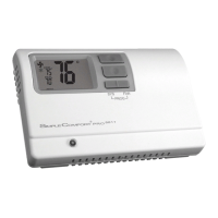
Illustration identifying the key physical components and terminals of the thermostat.

Wiring Diagram Configurations

Visual guides for connecting the thermostat to various heating and cooling system types.

Thermostat Specifications

Details electrical ratings, temperature control range, system compatibility, and timing.

Important Safety Precautions

Essential warnings and guidelines for safe handling and installation of the thermostat.

Package Contents and Required Tools

Lists items included in the product package and necessary tools for installation.

Removing the Existing Thermostat

Procedure for safely disconnecting and removing the old thermostat.

Operating the MP2010 L Thermostat

Installing and Changing Batteries

Instructions for battery installation and replacement for thermostat operation.

Operating Modes Explained

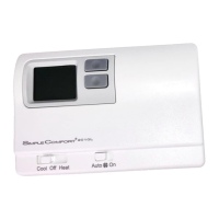
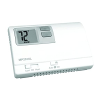
Description of available modes: OFF, Cool, and Heat, and their functions.

Configuration Mode Setup

Guide to setting up the thermostat to match specific system requirements.

ARC Detection Technology

Explanation of the Abnormal Rate of Change detection feature and error codes.

Troubleshooting Common Issues

Identifies symptoms, potential causes, and remedies for thermostat problems.

One-Year Limited Warranty

Details the warranty coverage, terms, and conditions for the thermostat.

Overview

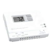
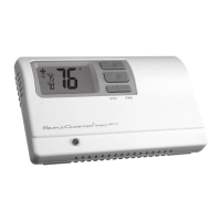
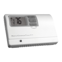
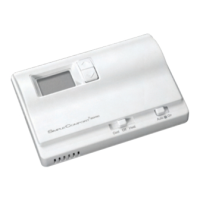
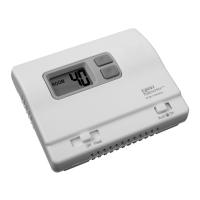
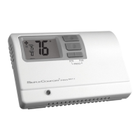
The ICM Controls MP2010L is a non-programmable managed property thermostat designed for residential and light commercial heating and cooling systems. It offers a straightforward interface and several features tailored for property management, including configurable temperature set points and a patented Abnormal Rate of Change (ARC) Detection Technology to prevent tampering. The thermostat is compatible with single-stage heat/cool and heat pump systems, and can be used with gas, oil, or electric heating sources. It can be powered by either 2 "AAA" batteries or hardwired to the system, with an optional common wire connection for hardwired setups.

Function Description

The MP2010L functions as a central control unit for managing indoor temperature. Users can select between heating, cooling, or an "OFF" mode, which disables both heating and cooling but allows manual fan operation. The thermostat features a large display with a backlight for easy readability, and users can choose to display temperature in Fahrenheit or Celsius.

A key feature is the Abnormal Rate of Change (ARC) Detection Technology. This patented system monitors temperature changes and, if it detects an abnormal rise or drop (suggesting tampering to trick the thermostat), it will initiate a lockout sequence. During this lockout, the display will show "Err" for an abnormal rise or "Erd" for an abnormal drop. Once normal operation resumes, the error message can be cleared by pressing any button. This helps property managers maintain consistent temperature control and prevent energy waste due to tenant manipulation.

The thermostat also includes a "Placebo Option," which allows the set point to be configured over a wide range, but the actual control will adhere to predefined maximum heat and minimum cool set points. This can give occupants the perception of more control while still enforcing property-specific temperature limits.

Usage Features

The MP2010L is designed for ease of use with simple up and down buttons for temperature adjustment and a mode switch to select between heat, cool, and off. The fan can be set to run continuously or automatically with the system.

Configuration of the thermostat is done through a dedicated "Configuration Mode." This mode is accessed by setting the system switch to "OFF" and pressing both the LEFT and RIGHT buttons simultaneously. Within this mode, property managers can customize various settings:

  • Temperature Scale: Choose between Fahrenheit or Celsius.
  • Temperature Differential: Adjust the number of degrees between the setpoint and when the system turns on, ranging from 1°F to 5°F (1°C to 3°C).
  • System Type: Configure for heat pump or non-heat pump systems. This setting is crucial as it enables a compressor time delay for heat pump applications.
  • Maximum Heat Setpoint: Set the highest allowable temperature for heating.
  • Minimum Cool Setpoint: Set the lowest allowable temperature for cooling.
  • Room Temperature Offset: Calibrate the displayed room temperature to match the actual room temperature, with adjustments from +9°F to -9°F (+5°C to -5°C). This is important for accuracy and should be adjusted before permanent lock.
  • Placebo Feature: Enable or disable the placebo option.
  • Permanent Lock Screen: This feature allows property managers to permanently lock certain configuration screens (specifically screens #4 through #8). Once locked, these settings cannot be changed without returning the thermostat to ICM Controls for reprogramming, which incurs a fee. This ensures long-term adherence to property policies.
  • Backlight: Configure whether the backlight is always off (for longer battery life) or turns on when a button is pressed.

The thermostat also incorporates a patented Thermal Intrusion Barrier, which helps improve temperature sensing accuracy by minimizing the impact of drafts or temperature fluctuations from within the wall cavity.

Maintenance Features

For battery-powered operation, the MP2010L will display "LO BAT" when the batteries need to be changed. It is recommended to replace the two "AAA" alkaline batteries at least once a year or whenever the low battery warning appears. Proper orientation of the batteries is crucial.

For hardwired installations, batteries are not required if a common wire is connected to the "C" terminal.

Troubleshooting guidance is provided in the manual for common issues such as a blank display, inoperative buttons, or the system not heating/cooling. This includes checking for 24 VAC power, verifying wiring, checking jumper positions (Gas/Electric, RC/RH, Non-HP/HP), adjusting temperature differential, and replacing batteries. The ARC detection system's "Err" or "Erd" messages are also addressed, indicating a lockout due to abnormal temperature changes. A reset button is available, which clears error messages but does not alter configuration settings.

ICM Controls MP2010L Specifications

General IconGeneral
ColorWhite
Voltage Rating24 VAC
DisplayDigital
Switch ActionSingle Pole
MountingWall Mount

Related product manuals