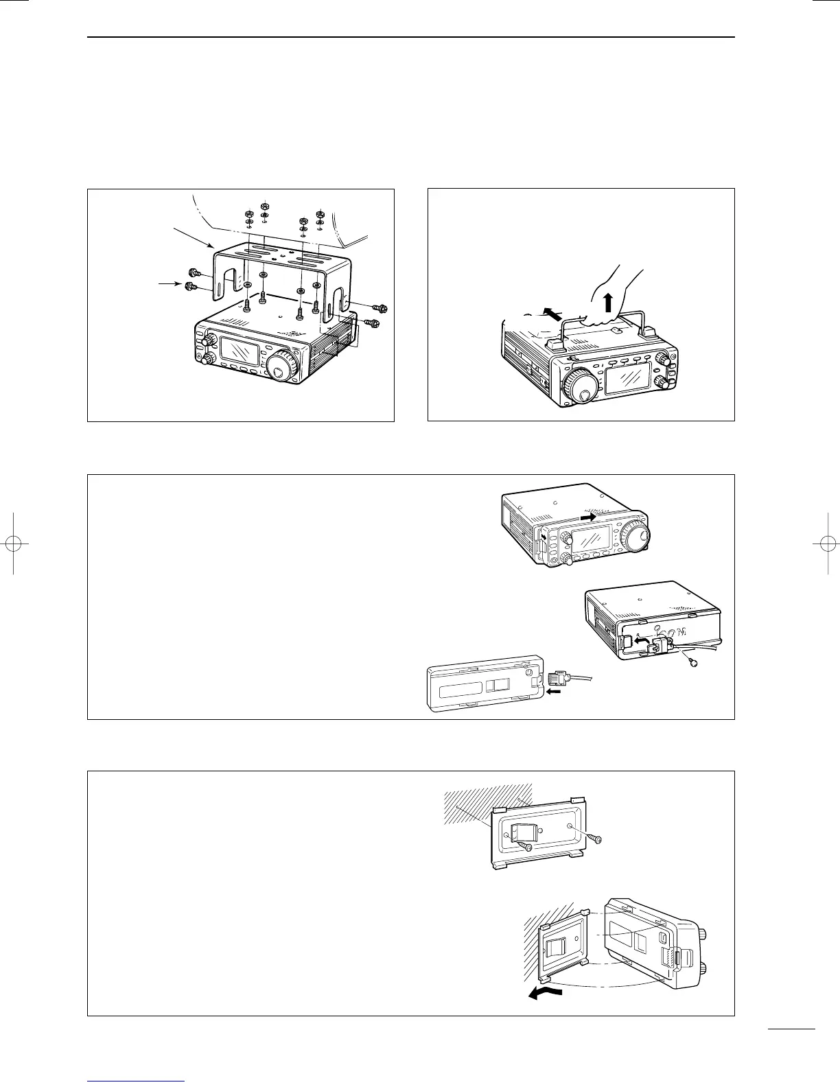
To raise the stand:
With the transceiver upside down, pull the stand
towards the rear panel and then upwards, as illus-
trated below.
10
2
INSTALLATION AND CONNECTIONS
■
IInnssttaallllaattiioonn
D
SSiinnggllee bbooddyy mmoouunnttiinngg
D
SSttaanndd
*CAUTION: Non-supplied screws (longer than 8 mm)
may damage the internal units.
MB-62
(optional)
Supplied with
the MB-62*
Pull back
then up
D
FFrroonntt ppaanneell sseeppaarraattiioonn
D
FFrroonntt ppaanneell mmoouunnttiinngg
➀ While pulling the panel release button towards
you, slide the front panel to the right (fig. 1).
➁ Attach the optional OPC-581 to the main body and
tighten the supplied screw as in fig. 2.
➂ Attach the other end of the OPC-581 to the
detached front panel as in fig. 3.
➀ Attach the MB-63 to a flat surface using the two
supplied screws (fig. 1).
➁ Fix the detached front panel to the MB-63 as illus-
trated in fig. 2.
BBee ccaarreeffuull
of the orientation of the MB-63, other-
wise, the front panel may become attached in the
opposite direction.
fig. 1
fig. 2
fig. 3
fig. 1
fig. 2
IC-706MKIIG.qxd 02.3.27 13:53 Page 10

 Loading...


