59
10
OOPPTTIIOONNAALL IINNSSTTAALLLLAATTIIOONNSS//SSEETTTTIINNGGSS
■
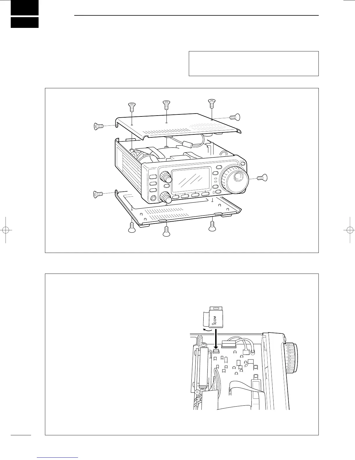
OOppeenniinngg tthhee ttrraannsscceeiivveerr ccaassee
To remove the transceiver case unscrew the 10
screws (5 in the top panel and 5 in the bottom panel)
as shown in the diagram below.
■
UUTT--110022
VVOOIICCEE SSYYNNTTHHEESSIIZZEERR UUNNIITT
The UT-102 announces the accessed band’s fre-
quency, mode, etc. (S-meter level can also be
announced—p. 55) in a clear, electronically generat-
ed voice, in English (or Japanese).
➀ Remove the top cover as shown above.
➁ Connect the UT-102 as shown in the diagram at
right (label side up).
➂ Replace the top cover.
UT-102
CCaauuttiioonn::
DDiissccoonnnneecctt
the DC power cable from
the transceiver before performing any work on the
transceiver.
IC-706MKIIG.qxd 02.3.27 13:53 Page 59

 Loading...


