1
PANEL DESCRIPTION
1-6
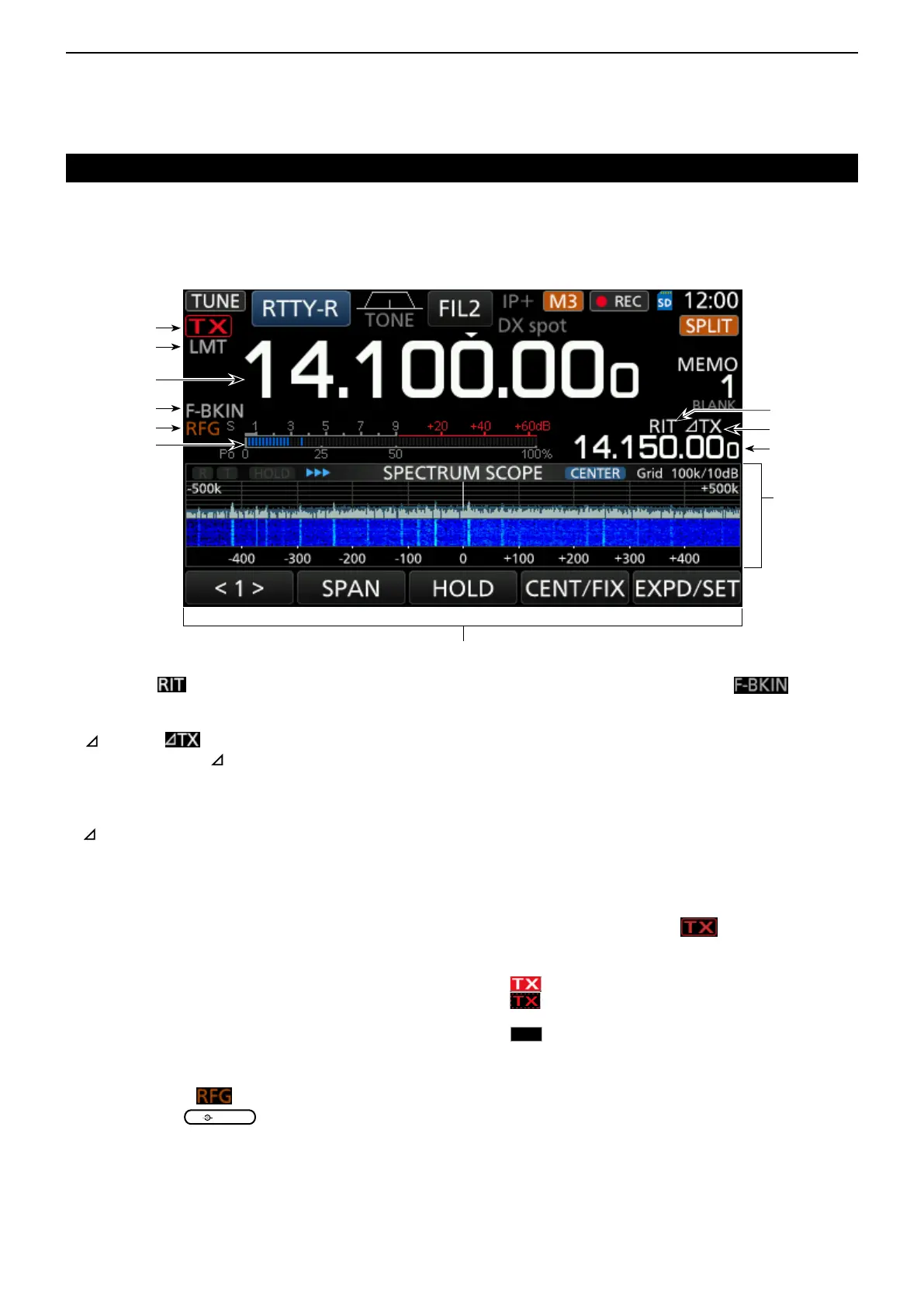
Touch screen (Continued)
!6 RIT ICON
(p. 4-2)
Appears while the RIT function is ON.
!7 TX ICON (p. 4-11)
Appears while the TX function is ON.
!8 SHIFT FREQUENCY READOUT
Displays the shift offset of the RIT (p. 4-2) or
TX (p. 4-11) functions, while the functions are ON.
!9 SPECTRUM SCOPE SCREEN (p. 5-2)
Displayed while using the Spectrum Scope.
@0 FUNCTION DISPLAY
Displays the operating parameters, modes,
frequencies and indicators, depending on your
selections.
@1 MULTI-FUNCTION METER (p. 3-11)
Displays various strengths and levels, depending
on the function you select.
@2 RF GAIN ICON
(p. 3-10)
Appears when
(outer) is set to the
counterclockwise from the 11 o’clock position. The
icon indicates that the RF gain is reduced.
@3 BK-IN/F-BKIN/VOX INDICATOR (p. 4-15)
Appears while the Semi Break-in, Full Break-in or
VOX function is ON.
@4 FREQUENCY READOUT (p. 3-4)
Displays the operating frequency.
@5 LMT DISPLAY (p. 13-4)
Appearsifthepowerampliertemperature
becomes extremely high and the Protection
function is activated after transmitting continuously
for long periods of time.
@6 TX STATUS INDICATOR (p. 3-10)
Displays the transmit status of the displayed
frequency.
• appears while transmitting.
•
appears when the selected frequency is outside of
the amateur band frequency range.
•
appears while transmitter is inhibited (p. 3-4)
@6
@3
@2
!7
!8
@4
@1
!9
@0
!6
@5

 Loading...


