3
1
PANEL DESCRIPTION
3
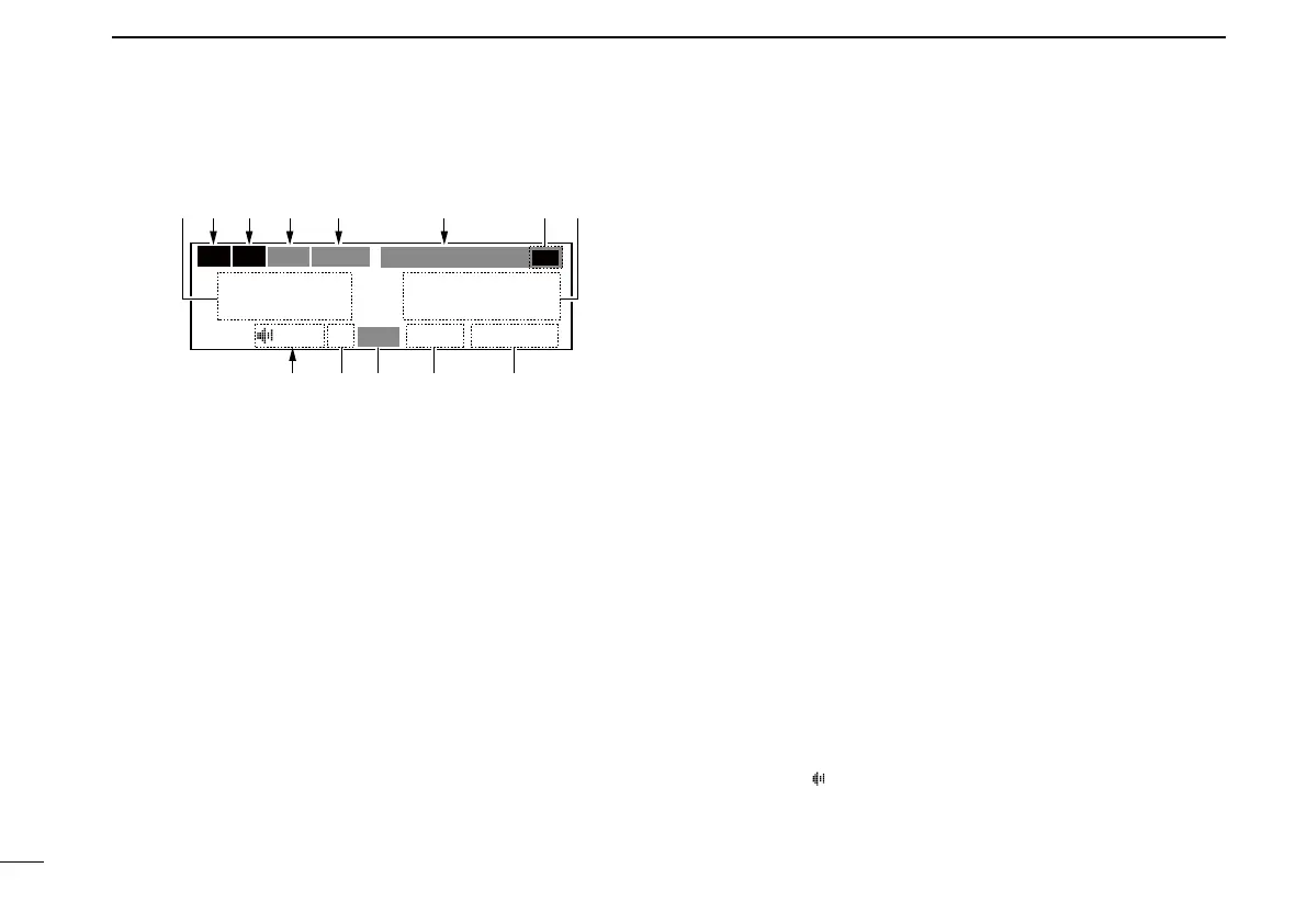
■ Function display
CH09 SAMPLE
TEST
121.525
118.00
RX
DUAL
MEMORY
RX
ICSTX
AU
LVD
etr y e
2
uq
1
w
0
q ACTIVE FREQUENCY READOUT
➥ Displays the active frequency. (p. 5)
➥ Displays the menu mode items in the menu mode.
(p. 17)
w TX INDICATOR
Displayed while transmitting. (p. 5)
e RX INDICATOR
➥ Displayed when receiving a signal on the active
frequency. (p. 5)
➥ Displayed when receiving a signal on the standby
frequency during Dualwatch operation. (p. 13)
➥ Displayed when opening the active frequency’s
squelch function. (p. 5)
r INTERCOM READOUT
Displays “ICS” when the intercom function is in use.
(p. 14)
t DUALWATCH READOUT
Displays “DUAL” when the Dualwatch function is ON.
(p. 13)
y MEMORY TYPE READOUT
➥ Displays “MEMORY” when the regular memory
channel is selected. (p. 8)
➥ Displays “GRP01”–“GRP05” when the group
memory channel is selected. (p. 8)
The group name is also displayed if the name has
been entered.
➥ Displays “HISTORY” when the history memory
channel is selected. (p. 12)
➥ Displays “WEATHER” when the weather memory
channel is selected. (p. 12)
u STANDBY FREQUENCY READOUT
➥ Displays the standby frequency. (p. 5)
➥ Displays options in the menu mode. (p. 17)
i CHANNEL NAME READOUT
Displays the channel name in the memory mode. (p. 10)
o MEMORY CHANNEL READOUT
Displays the selected memory channel number in the
memory mode. (p. 8)
!0 LOW VOLTAGE INDICATOR
Displays “LVD” when the voltage is low. (p. 16)
!1 SQUELCH MODE READOUT
Displays the squelch mode status. (pp. 6, 19)
!2 TEST INDICATOR
Displays “
”
while the squelch test function is ON.
(p. 14)