4 -4
RX AF CIRCUITS (LOGIC UNIT)
<A BAND>
The AF signals from the FM/AM demodulator circuits are
passed through the mode SW (M: IC500D) and one of the
AF filters (IC502 and Q501, or, Q502 only) whose audio
frequency response is set as stable for each RX mode (FM/
AM or WFM).
FM/AM-demodulated AF signals are filtered by IC502, and
FM (WFM)-demodulated AF signals are filtered by Q502.
The filtered AF signals are passed through the D/A
converter (DAC; IC600, pins 21, 22; 24, 23) for level
adjustment. The level-adjusted AF signals are entered to the
LOGIC UNIT via the RX AF mute SW (M: IC700, pins 8, 9),
and applied to the AF power AMP (IC400) to obtain audio
output power. The power-amplified AF signals are applied to
the internal speaker or output from [DATA/SP/MIC] jack.
<B BAND>
• FM MODE
The FM-demodulated AF signals from the mute SW (M:
IC500B) are passed through the mode SW (IC500A) and
AF filter (M: IC501).
• AM MODE
The AM-demodulated AF signals from the AM detector (M:
Q203, 204, D205) are directly passed through the AF filter
(M: IC501, pin 2).
• DV MODE
The FM-demodulated signals from the IF IC (M: IC200) are
passed through the tone filter (M: IC250). The filtered signals
are applied to the modem (IC501) via the tone selector (M:
IC703) and buffer (IC504B), to be converted into the DV data.
The DV data is applied to the CPU (IC1), and converted into
the AMBE signals. The AMBE signal is then applied to the
DSP CODEC IC (IC506) and decoded. The decoded AMBE
signals are converted into the analog audio signal by liner
CODEC IC (IC503). The converted AF signals are passed
through the mode SW (M: IC500A) and AF filter (M: IC501).
The filtered AF signals are passed through the D/A
converter (DAC; M: IC600, pins 13, 14; 16, 15) for level
adjustment. The level-adjusted AF signals are entered to
the LOGIC UNIT via RX AF mute SW (M: IC700C/D), and
applied to the AF power AMP (IC400) to obtain audio output
power. The power-amplified AF signals are applied to the
internal speaker or output from [DATA/SP/MIC] jack.
SP
AF
AMP
BUFF
LPF
LPF
CPU
Q400,401
POWER AMP
CONTROLLER
MODEM
DSP
CODEC
LINEAR
CODEC
IC600
IC400
LOGIC UNIT MAIN UNIT
CHASSIS
[DATA/MIC/SP]
IC503
IC506
IC504B
IC501
IC1
SP
SW
FIL
IC501
SEL
SW
IC150
SW
FILTER
FILTER
FIL
IC500A
M ODE
TONE
IC500D
M ODE
IC250
AF
IC703
<B-BAND>
FM-demodulated
AF signals from IF IC (IC200)
<B-BAND>
FM-demodulated
AF signals from MUTE SW (IC500)
FM-demodulated AF signals from IF IC (IC200)
Level-adjusted AF signals to IF IC (IC200)
Level-adjusted AF signals to IF IC (IC100)
FM-demodulated AF signals from IF IC (IC100)
<B-BAND>
AM-demodulated
AF signals from AM demodulator (D205)
<A-BAND>
AM/FM-demodulated AF signals from
AM demodulator (D105)/mute SW (IC500)
TONE
TONE
AF
D/A
AFON
SPSW
Q402-405
IC502
AF
FIL
Q502
RX AF MUTE
SW
11
13
1
2
3
8
7
11
9
2
2
2
7
14
6711
20,21
72,73
3297
42
16
15
8
2
11
37
10
6
9,10
IC700C/D:CD4066
22
21
11
12
9
10
24
23
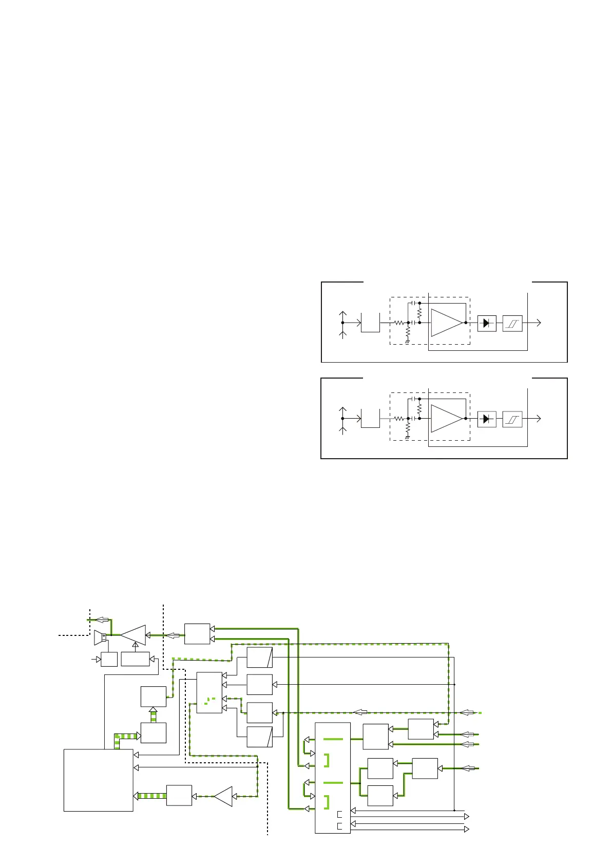
SQUELCH CIRCUIT
The squelch circuit cuts off the AF output signals when
no RF signals are received. Detecting noise components
(approx. 30 kHz signals) in the demodulated AF signals, the
squelch circuit stops audio signals being emitted.
A portion of FM-demodulated AF signal from the IF IC
(M: IC100/IC200) is passed through the DAC (M: IC600)
for level (=threshould) adjustment. The level-adjusted AF
signals are passed through the noise filter (IC100, pins 7, 8
and R111–113, C121, 122/IC200, pins 7, 8 and R214–216,
C221, 222) to filter the noise components (approx. 30 kHz
signals) only. The noise components are rectified to produce
DC voltage corresponding to the noise level.
If the noise level is higher than the preset one, the internal
comparator set the "ANOISE"/"BNOISE" signal to the
CPU to "High", then the CPU turns the "AFON" signal
which controlls the AF power AMP (L: IC400) to "Low," to
inactivate the AF power AMP (L: IC400). At the same time,
the CPU turns the "ARMUTE"/"BRMUTE" signal which
controlls the RX AF mute SW (L: IC700) to "Low," to cut-off
the RX AF line.
DAC
Noise
AMP
Noise filter
From IF IC
(IC100, Pin16)
To RX AF circuits
Noise
detector
Com-
parator
NOISE SQUELCH DIAGRAM (A BAND)
“ANOIS”
IC600
IC100
9
8
7
13
10
DAC
Noise
AMP
Noise filter
From IF IC
(IC200, Pin16)
To RX AF circuits
Noise
detector
Com-
parator
NOISE SQUELCH DIAGRAM (B BAND)
“BNOIS”
IC600
IC200
9
8
7
13
10
• RX AF CIRCUITS