29
5 CONNECTION AND INSTALLATION
New2001
DD
UT-109/UT-110/UT-117S installation
Install the optional unit as below.
qTurn power off, then disconnect the DC power cable.
wUnscrew the 4 screws, then remove the bottom cover.
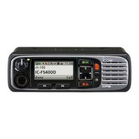
eCut the print patterns on the PCB at the transmit mic cir-
cuit (MIC) and receive AF circuit (AFO) as shown in the di-
agram below.
rInstall the scrambler unit as described in page 28.
tAttach the bottom cover and screws to their original posi-
tion, then connect the DC power cable.
NOTE: Be sure to re-solder above print
patterns, when you remove the scrambler
unit. Otherwise no TX modulation or AF
output is available.
DD
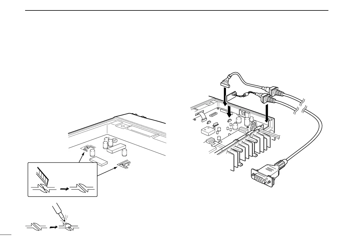
OPC-617/822 installation
Either the optional OPC-617
ACC CABLE
or OPC-822
INTER
-
FACE CABLE
can be installed.
Install the OPC-617 or OPC-822 as shown bellow.
IC-F510 Series_BIIS-2.qxd 06.7.13 1:31 PM Page 29 (1,1)

 Loading...