4 - 5
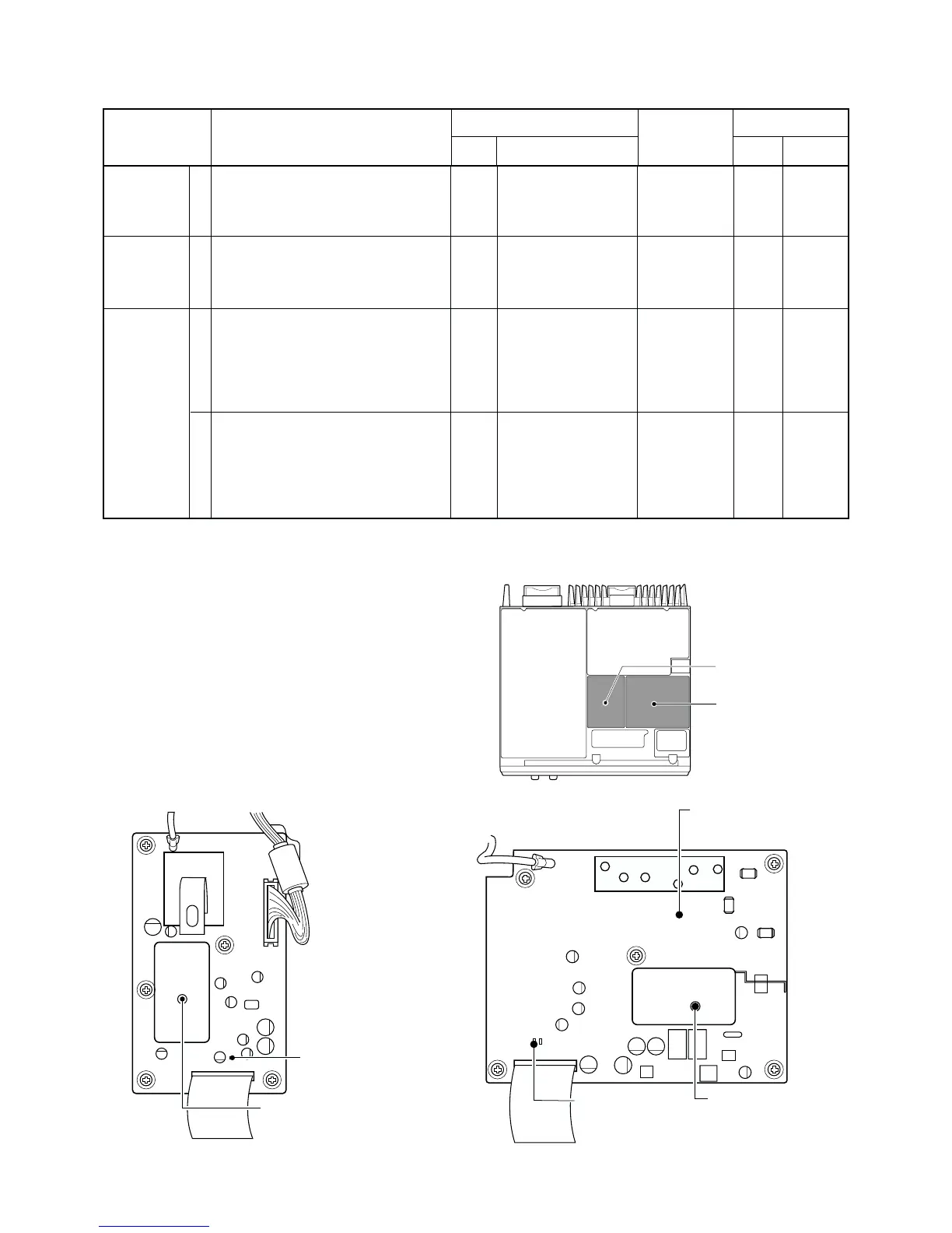
4-2 PLL ADJUSTMENT
TX VCO LOCK
VOLTAGE
RX VCO LOCK
VOLTAGE
REFERENCE
FREQUENCY
1
1
1
2
• LCD display :
A01 LW TXREF 127
• Receiving
• LCD display :
A01 LW TXREF 127
• Receiving
• Wait for 5 minutes after power ON.
• LCD display :
A01 LW TXREF
• Connect the RF power meter or 50 Ω
dummy load to the [TX] antenna con-
nector.
• Transmitting
• Push the [PROG] button.
• LCD display :
A01 LW RXREF
• Receiving
TX
RX
REAR
panel
RX
Connect the digital
multi meter or oscillo-
scope to check point
CP1.
Connect the digital
multi meter or oscillo-
scope to check point
CP1.
Loosely couple the
frequency counter to
the [TX] antenna con-
nector.
Connect the frequen-
cy counter to check
point HJ4.
1.0 V 1, 2, 4
0.8 V 3, 5
4.3 V
1, 3, 4, 5
3.5 V
2
400.2750 MHz
1, 4
430.2750 MHz
2
450.2750 MHz
3, 5
359.2750 MHz
1, 4
379.9250 MHz
2
409.9250 MHz
3, 5
TVCO
RVCO
FRONT
FRONT
C17
C17
[PRT/BASE]
/[MONI]
[PRT/BASE]
/[MONI]
ADJUSTMENT ADJUSTMENT CONDITIONS
UNIT LOCATION
VALUE
UNIT ADJUST
MEASUREMENT ADJUSTMENT
• TOP VIEW
• RX UNIT TOP VIEW
• TX UNIT TOP VIEW
1: [USA1], [GEN1], [GEN5], [EUR1] 4: [FRG1]
2: [GEN2], [GEN6] 5: [FRG3]
3: [USA3], [GEN3], [GEN7], [EUR3]

 Loading...


