3 - 1
SECTION 3
DISASSEMBLY INSTRUCTION
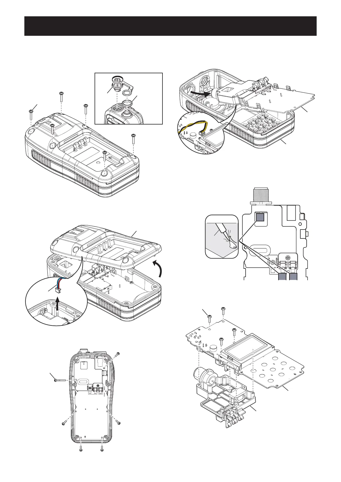
1. REMOVING THE PCB
1) Remove the battery pack from the transceiver.
2) Remove the DC cap and antenna nut.
3) Remove 6 screws from the rear panel.
2. REMOVING THE CHASSIS
1) Unsolder 3 points shown.
4) CAREFULLY lift the rear panel up and unplug the
wet sensor wire.
2) Remove 4 screws from the PCB, and then remove
the CHASSIS.
5) Remove 6 screws from the PCB.
DC cap
Antenna nut
6 screws
Rear panel
Wet sensor
wire
6 screws
Front panel
PCB
SP cable
UNSOLDER
Solder
remover
Chassis
4 screws
Chassis
PCB
6) CAREFULLY lift the PCB out of the front panel, and
then turn it over in order to unplug the speaker wire.
(Continued on the right above.)