4 - 3
4-3 PLL CIRCUIT (MAIN UNIT)
A PLL circuit provides stable oscillation of the transmit fre-
quency and receive 1st LO frequency. The PLL output com-
pares the phase of the divided VCO frequency to the refer-
ence frequency. The PLL output frequency is controlled by
the divided ratio (N-data) of a programmable divider.
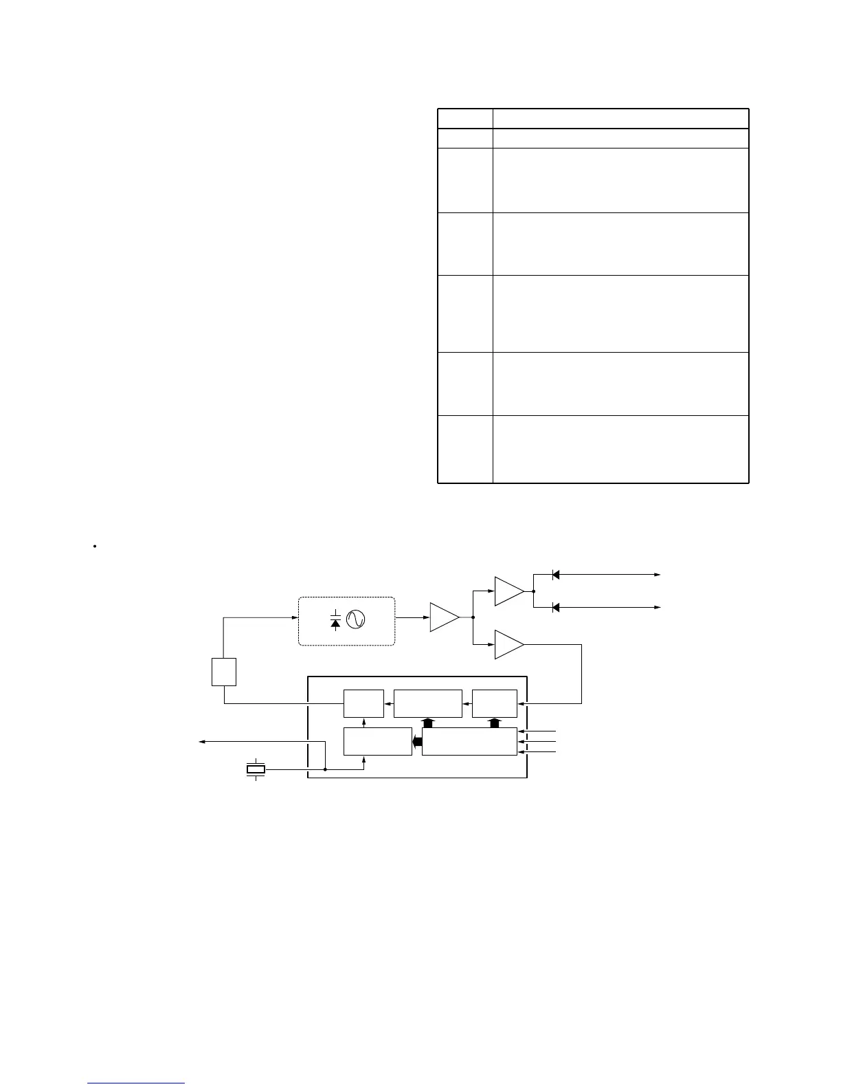
The PLL circuit contains a VCO (Q21, Q22, D22, D23). The
oscillated signal is amplified at the buffer-amplifiers (Q23,
Q25) and then applied to the PLL IC (IC1, pin 19).
The PLL IC contains the prescalers, programmable counter,
programmable divider, phase selector and etc. The entered
signal is divided at the prescaler and programmable counter
sections by the N-data ratio from the CPU. The divided sig-
nal is detected on phase at the phase detector using the ref-
erence frequency.
If the oscillated signal drifts, the phase of its frequency
changes from the reference frequency, causing a lock volt-
age changes to compensate for the drift in the oscillated fre-
quency.
A portion of the VCO signal is amplified at buffer-amplifiers
(Q23, Q24) and is then applied to the receive 1st mixer
(Q150) or transmit driver via the TX/RX switching diode
(D50, D51).
LINE
VCC
CPU5V
5V
R5V
V5V
T5V
DESCRIPTION
The voltage from the attached battery pack.
Common 5 V converted from the VCC line by the
CPU5V regulator circuit (IC220).
The output voltage is applied to the CPU
(IC360), REG5V regulator, etc.
Common 5V converted from the VCC line by the
5V regulator circuit (Q223–Q225).
The output voltage is applied to the D/A convert-
er (IC190) and PLL IC (IC1), etc.
Receive 5V converted from the 5V line by the R5
regulator circuit (Q221).
The regulated voltage is applied to the MOD
MUTE circuit (Q20, D20, D21) and receiver cir-
cuit.
Common 5V converted from the 5V line by the
V5 regulator circuit (Q220).
The regulated voltage is applied to the VCO cir-
cuit
Transmit 5V converted from the 5V line by the T5
regulator circuit (Q222).
The regulated voltage is applied to the transmit-
ter circuit.
4-4 POWER SUPPLY CIRCUITS
VOLTAGE LINES