4
2
PANEL DESCRIPTION
New2001
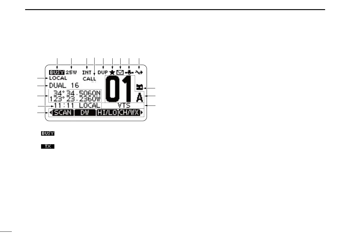
■ Function display
!4
!6
!5
qw ietr
!0
you
!1
!2
!3
!7
q BUSY/TRANSMIT ICON (p. 12)
“ ➥
” is displayed when receiving a signal or when
the squelch is open.
“ ➥
” is displayed while transmitting.
w POWER ICON (p. 12)
“25W” is displayed when high power is selected. ➥
“1W” is displayed when low power is selected. ➥
e CHANNEL GROUP ICON (p. 10)
Shows which channel group is selected, INT, USA, CAN,
ATIS or DSC, depending on the version.
WX is displayed when the weather channel is select- ➥
ed.*
*For only U.S.A. and Australian version transceivers.
r CALL CHANNEL ICON (p. 9)
Displayed when the Call channel is selected.
t DUPLEX ICON (p. 10)
Displayed when a duplex channel is selected.
y FAVORITE CHANNEL ICON (p. 17)
Displayed when a Favorite (Tag) channel is selected.
u MESSAGE ICON (p. 60)
Blinks when there is an unread DSC message.
i GPS ICON
Stays ON when the built-in GPS receiver* or an exter- ➥
nal GPS receiver is receiving valid position data.
*For only IC-M323G and IC-M324G.
Blinks when searching for valid position data. ➥
o SWITCH ICON (p. 63)
Displayed when the “CH 16 SWITCH” in DSC Settings is
set to OFF.
!0 LOW BATTERY ICON
Blinks when the battery voltage drops to approximately
10 V DC or less.
!1 CHANNEL NUMBER READOUT
Shows the selected operating channel number.
•Whenasimplexchannelisselected,“A”isdisplayed.
!2 CHANNEL NAME FIELD
The channel name is displayed, if entered. (p. 13)