5 - 6
JIG cable
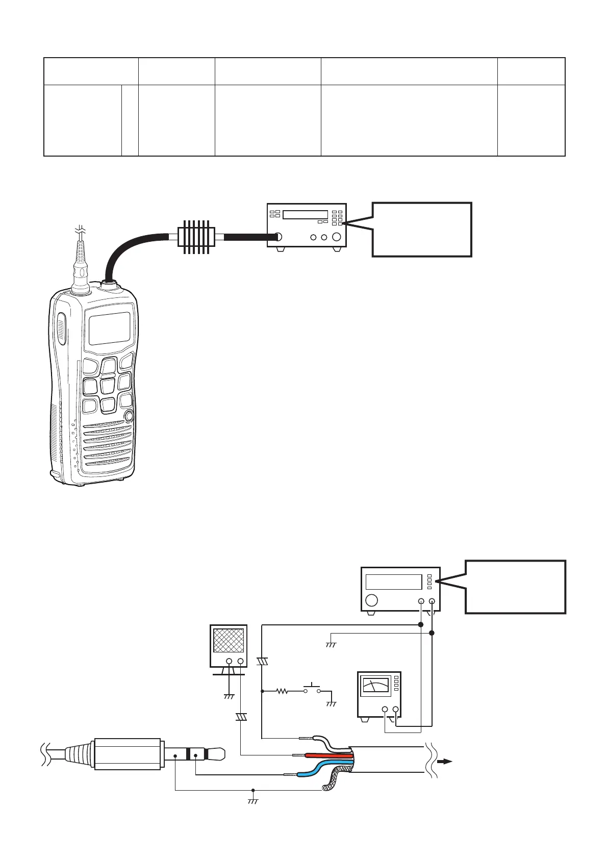
ATTENUATOR
(30 dB/10 W)
MODULATION ANALYZER
(0.1–300 MHz)
SETTING;
HPF : OFF
LPF : 20 kHz
De-emphasis : OFF
Detector : (P-P)/2
ADJUSTMENT
ADJUSTMENT
ITEM
TRANSCEIVER’S
CONDITION
OPERATION VALUE
DEVIATION 1
[MOD]
• CH. : 16
• TX power : Low
• Transmitting
1) Connect a Modulation analyzer to
the antenna connector through an
Attenuator.
2) Apply specified audio signals through
the JIG cable. (see the illust below).
3) Adjust the deviation.
±4.30 to ±4.40
kHz
Select an adjustment item using [
↑
] / [
↓
] keys, then set to the specifi ed value using [
←
] / [
→
] keys on the connected PC’s keyboard.
5-4 TRANSMIT ADJUSTMENTS (continued)
+−
EXT. SPEAKER
(1 W/8 Ω)
SETTING;
Frequency : 1 kHz
Level : 25 mVrms
Waveform : Sine wave
AUDIO GENERATOR
(300–3000 Hz/1–500 mV)
+−
+−
AC
MILLIVOLT METER
(10 mV to 10 V)
+
47 µF
+
4.7 µF
OPC-478/U/UC
WHITE (MIC)
(MIC line)
(SP line)
BLUE (CLONE)
SHIELD (GND)
(CLONE line)
OPC-1668
(Parts No.: 8900016260)
To the transceiver
RED (AFOUT)
PTT
33 k
Ω
¤ JIG CABLE

 Loading...


