85
10
CONNECTIONS AND MAINTENANCE
r DC POWER CONNECTOR
Connects to a 13.8 V DC power source. (+: Red, –: Black)
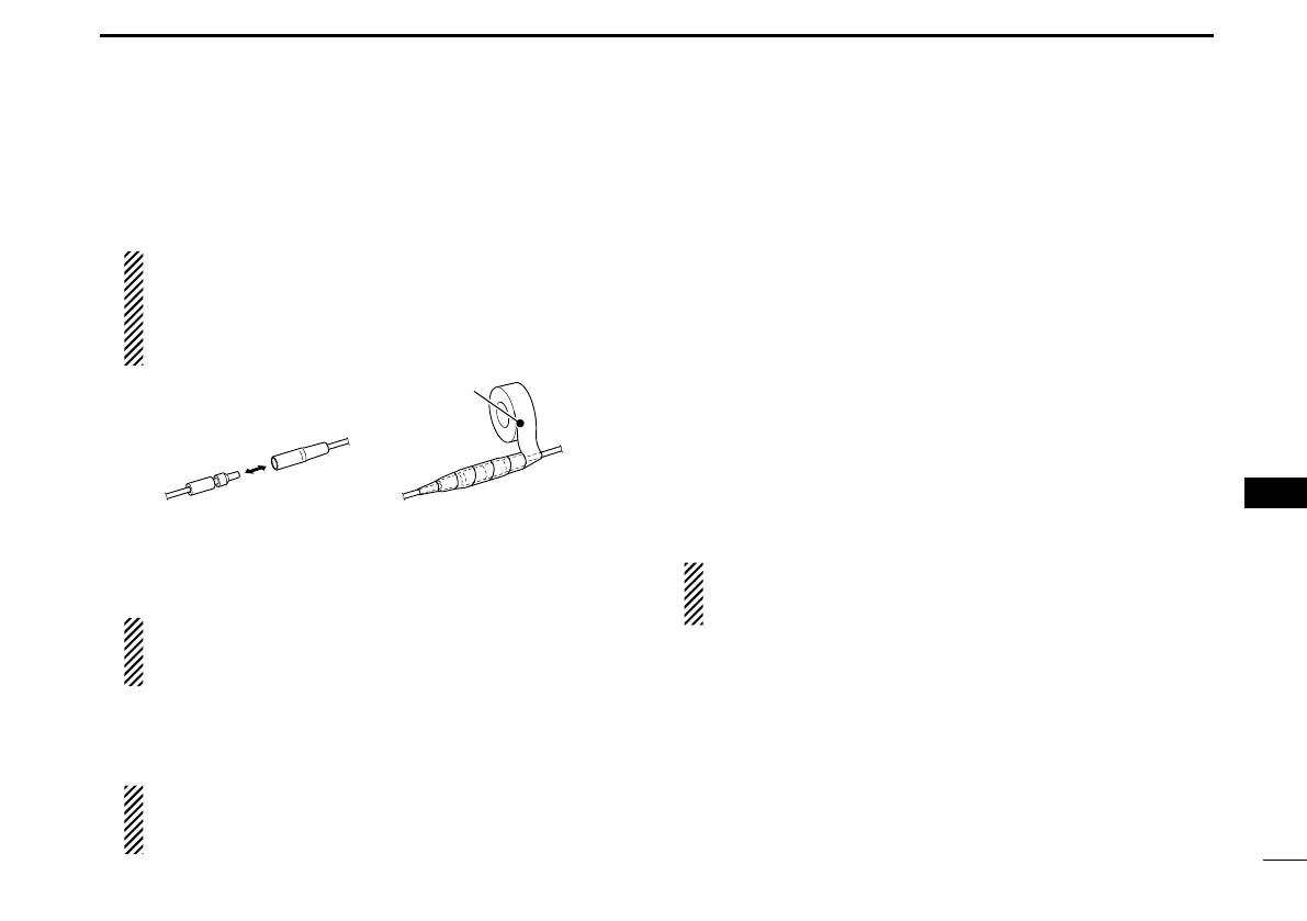
CAUTION: After connecting the DC power cable,
NMEA leads, external speaker leads, and PA speaker
leads, cover the connector and leads with an vulcaniz-
ing tape, as shown below, to prevent water seeping into
the connection.
tape
t GROUND TERMINAL
Connects to a vessel ground to prevent electrical shocks
and interference from other equipment occurring.
Use a PH M3 × 6 screw (user supplied).
NOTE for the IC-M423, IC-M423G, IC-M424, and IC-
M424G: The location of the ground terminal is the same
as the GPS antenna connector on the IC-M423GE.
y GPS ANTENNA CONNECTOR
Connects to the supplied GPS antenna. (For only the IC-
M423GE)
NOTE:
Be sure the GPS antenna is positioned where it
has a clear view to receive signal from satellites, and
fixed using the supplied double-sided adhesive pad.
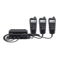
u COMMAND MICROPHONE JACK
Connects to the optional Command microphone. (p. 89)
D Connecting to the MA-500TR/MA-510TR
An Individual DSC call can be made to the AIS target using
the transponder without entering the target’s MMSI code.
See the transponder’s instruction manual for connection de-
tails.
Connect each lead to the appropriate lead of the OPC-2014
as follows.
• Listener A (Data-H) (Yellow): To lead 3.
• Listener B (Data-L) (Green): To lead 2.
• Talker A (Data-H) (White): To lead 5.
• Talker B (Data-L) (Brown): To lead 4.
NOTE:
This instruction is for the MA-500TR. See the MA-
510TR Instruction manual for the MA-510TR
’
s connecting
instructions.
1
2
3
4
5
6
7
8
9
10
11
12
13
14
15
16