4 - 2
• TX AF CIRCUITS
• MODULATION CIRCUITS
• TX AMP AND APC CIRCUITS
From the demodulator circuit
LPF
LIMIT
AMP
AMP
AF
MUTE
AF
MUTE
PRE
ENPHA
D/A
MIC
J291
IC190
IC200A
IC200B
INMIC
EXTMIC
MAIN UNIT
MOD
IC260A
IC260C
MC250
Int.MIC
IC200D
To the modulation circuit
MICO
MSENS
Ext.MIC
AF
SW
NOISE CANCEL IC
IC382
IC380
LPF
ANT
SW
J1
PWR
AMP
DRIVE
PRE
BUFF
APC
CTRL
D52
Q53 Q54
From the VCO
Q50
PWR
DET
D91
IC50
To the RX circuit
TDETV
RF UNIT
LO
SW
BUFF
BUFF
D50
To the TX AMP circuit
Q24
Q23
Q21,Q22
D2-D22
MOD
RF UNIT
From the TX AF circuit
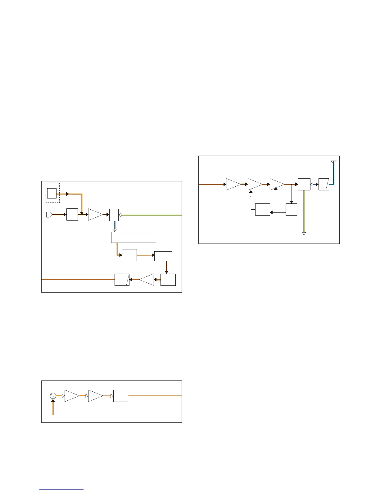
4-2 TRANSMIT CIRCUITS
TX AF CIRCUIT (MAIN UNIT)
The AF signal from the internal microphone (MC250) is
passed through the MIC mute SW (IC260A, pins 1, 2), and
then applied to the MIC AMP (IC200B, pin 6).
The MIC signal from the external microphone is directory ap-
plied to the MIC AMP (IC200B, pin 6), through J290.
The amplifi ed AF signal is passed through the AF SW (IC380,
pins 6, 1) and applied to the noise canceller IC (IC382,
pin 36).
The processed AF signal is passed through the AF mute SW
(IC260C, pins 8, 9), and then applied to the D/A converter
(IC190, pin 13) to adjust the level.
The level-adjusted AF signal is passed through the pre-em-
phasis circuit (R201, C385), and then amplifi ed by the limiter
AMP (IC200A) which limits the amplitude of AF signal to pre-
vent over deviation. The amplitude-limited signal is passed
through the LPF (IC200D, pins 12, 14), and then applied to
the modulation circuits on the RF UNIT.
MODULATION CIRCUIT (RF UNIT)
The AF signal from the TX AF circuits is applied to the VCO
(Q21, Q22, and D20–D22). The modulation signal is applied
to D20, for Frequency Modulation.
The modulated VCO output signal is passed through the buf-
fers (Q23 and Q24), and then applied to the TX AMP circuits
as a TX signal, through the LO SW (D50).
TX AMP CIRCUIT (MAIN UNIT)
The TX signal is sequentially amplifi ed by the buffer (Q50),
YGR (Q53) and power (Q54) AMPs, and then passed
through two LPFs (L57, C70, C71 and L80, C81, C82), TX
output power detector (D91), ANT SW (D52), and a two stage
LPF (L81, L82, C83–C86 and C89), before being sent to the
antenna.
APC CIRCUIT (MAIN UNIT)
The voltage produced at two LPFs (L57, C70, C71 and L80,
C81, C82) is rectifi ed by D91, and is used as the TX power
sensing voltage.
The voltage is applied to the APC AMP (IC50, pin 3), and the
output voltage controls the gain of the pre-driver (Q53) and
power (Q54) AMPs, to keep the TX output power constant.
 Loading...