EasyManuals Logo

Icom IC-R10 Service Manual

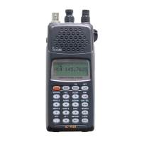
Icom IC-R10
56 pages
To Next Page IconTo Next Page
To Previous Page IconTo Previous Page
Page #14 background imageLoading...
Page #14 background image
5-1
PLL AND BFO
ADJUSTMENT
ADJUSTMENT ADJUSTMENT
CONDITIONS
MEASUREMENT
VALUE
ADJUSTMENT
UNIT LOCATION
UNIT ADJUST
1ST
VCO
LOCK
VOLTAGE
1
Displayed
frequency: 200 MHz
:
534 MHz
: 610 MHz
: 846 MHz
Receiving
MAIN Connect a
voltmeter
(1
MQ impedance) to
the
check point LVI.
More than 0.2 V
Verify
2
Displayed frequency: 533
MHz
:
609
MHz
: 845 MHz
:
895
MHz
Receiving
Less
than 3.3 V
2ND VCO
LOCK
VOLTAGE
1
Displayed frequency: 100 MHz
Mode : SSB
Noise Blanker :
ON
Receiving
MAIN
Connect
a
voltmeter
(1
MQ impedance) to
the check point 21 LV.
Less
than 2.5 V Verify
2
Displayed frequency: 500
MHz
Receiving
More than 0.6 V
3
Displayed frequency: 100
MHz
Mode
: SSB
Noise
Blanker : ON
Receiving
Connect a
voltmeter
(1
MQ
impedance) to
the check point
22
LV.
Less
than 2.5 V
4
Displayed frequency: 500
MHz
Receiving
More than 0.6 V
1ST
REFERENCE
FREQUENCY
1
Displayed
frequency: Any
Mode
: Any
Receiving
MAIN Connect a
frequency
counter
to
the check
point REF.
10.24500 MHz RF C501
BFO
FREQUENCY
1
Displayed frequency:
144.0000 MHz
Mode : LSB
Receiving
LOGIC Connect a
frequency
counter
to
the check
point CPI
.
453.500 kHz LOGIC R239
2
Mode
: USB
Receiving
456.500
kHz R243
5-1

Other manuals for Icom IC-R10

Questions and Answers:

Question and Answer IconNeed help?

Do you have a question about the Icom IC-R10 and is the answer not in the manual?

Icom IC-R10 Specifications

General IconGeneral
BrandIcom
ModelIC-R10
CategoryReceiver
LanguageEnglish

Related product manuals