RECEIVER ADJUSTMENT (Continued)
MEASUREMENT
ADJUSTMENT
POINT
ADJUSTMENT
ADJUSTMENT CONDITIONS VALUE
UNIT LOCATION
UNIT ADJUST
S-METER
4
•Apply
no signal
to
ANTENNA
FRONT
METER
Approx.
51
Verify
•FM
CONNECTOR. PANEL
(narrow)
NOTE:
R80
controls
total
gain adjustment, so
it
is not be touched as noise
will
increase. However,
it
may be
necessary
to
adjust
R80
under the following
condition:
If
the METER indicates more than
51
in step
4,
adjust
R51
to
51
and then
follow
step 1 again.
After
completing
the above adjustment, adjust
R80
to
59
with
0.1
mV input.
S-METER 1
•Display
freq.: 762.0000 MHz FRONT
METER
S9+60dB
IF
R28
•FM
(wide)
• Mode:
FM
(wide)
PANEL
•Apply
RF
signal
to
ANTENNA
CONNECTOR.
Level: 100mV
(-?dBm)
Dev.:
±3.5kHz
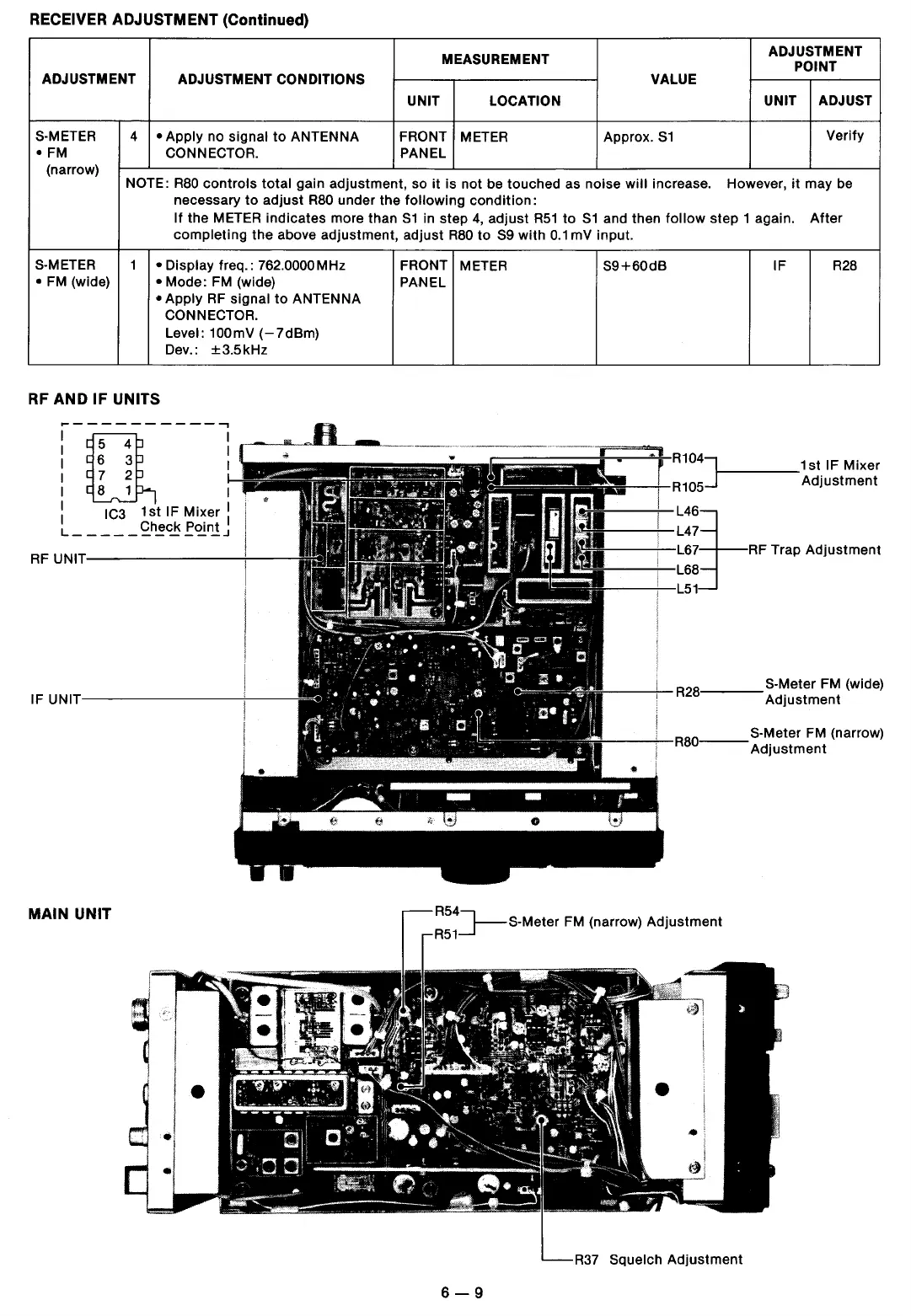
RF
AND IF UNITS
~----------...,
i[l
I 2
I 1
: IC3
1st
IF Mixer :
L_
- - - -
~h~C!
~~l!!J
...
r*
RR110045]1-----
.
1st
IF Mixer
-~-+-
Adjustment
RF
UNIT---------+---
IF
UNIT---------+---
r------;--
R
28
,
___
S-Meter
FM
(wide)
Adjustment
R54]-
S-Meter
FM
(narrow)
Adjustment
R51
MAIN UNIT
R37
Squelch
Adjustment
6-9
 Loading...