(3) BPF3 (250.0000
-511.9999
MHz)
The 250.0000
-5
11.9999 MHz signals pass through a
high-pass filt er (L32, L69, C34, C35. C51, C133) to sup-
press the interference signaIs in low frequencies. The
filter cuts out the 240 MHz frequencies. The filtered
signals are applied to an
RF
amplifier
(a3
) via a tuned
bandpass filter (D21. D22, L33. L34). The amplified
signaIs are applied to a 2nd RF amplifier (
07
) through
another tuned bandpass filter (D23, D24, L36, L37).
D21
---D24 employ varactor diodes which are controlled
by the PLL Joek voltage. The voltaçe is current-amplified
at the DC amplifier circuit (IC3a. IC
2a
) and is then
appüed 10 Ihe varactor diodes. These varactor diodes
tune Ihe center frequency of an RF passband tor wide
bandwidth receiving and goed image response rejection.
(4) BPF4 (512.0000
-1024.9999
MHz)
RF relays are used instead of a diode swi
tc
hing system
tor signals above 512 MHz. To drive these relays, Q14
and
015
are used as current amplifiers.
The 512.0000
-10
24.9999 MHz signals pass through a
parallel resonant circuit (D26, L39, C45) to suppress half
of Ihe receive frequen
cy
interference signaIs and are
then a
pp
lied to an RF circuit (0 4) via a tuned bandpass
filter. The amplified signaIs are applied to a 2nd RF
amp
lifier (
07
) through a tuned bandpass filter. The tuned
bandpass filters consist of a strip line and
0 27
-03
0 and
ensure stabie operation at high frequencies.
The voltage is current-amplified at the
De amplifier circuit
(/C3a. IC3b) and is then applied to the varactor diode
s.
These varactor diodes tune the center frequency of an
RF
passband tor wide bandwidth receiving and goed image
response rejection.
The signaIs from the tuned notch
circu
it are applied to a
low-pass fiiter (strip line, C78, C82, C85. C89,
CI
3?) to
suppress high harmonie components
of
the 1st
LO
signa
!.
The filtered signals
are
applied to a 1st mixer circuit.
3·1·5 TUNED CONTROL CIRCUIT (RF UNIT)
The tuned control
cir
cuit
converts the PLL loek voltage to
tuned voltage
tor the BPFI - BPF4 on the
RF
UNIT and
the tuned notch
circ
uit on the
TRAP
UNIT.
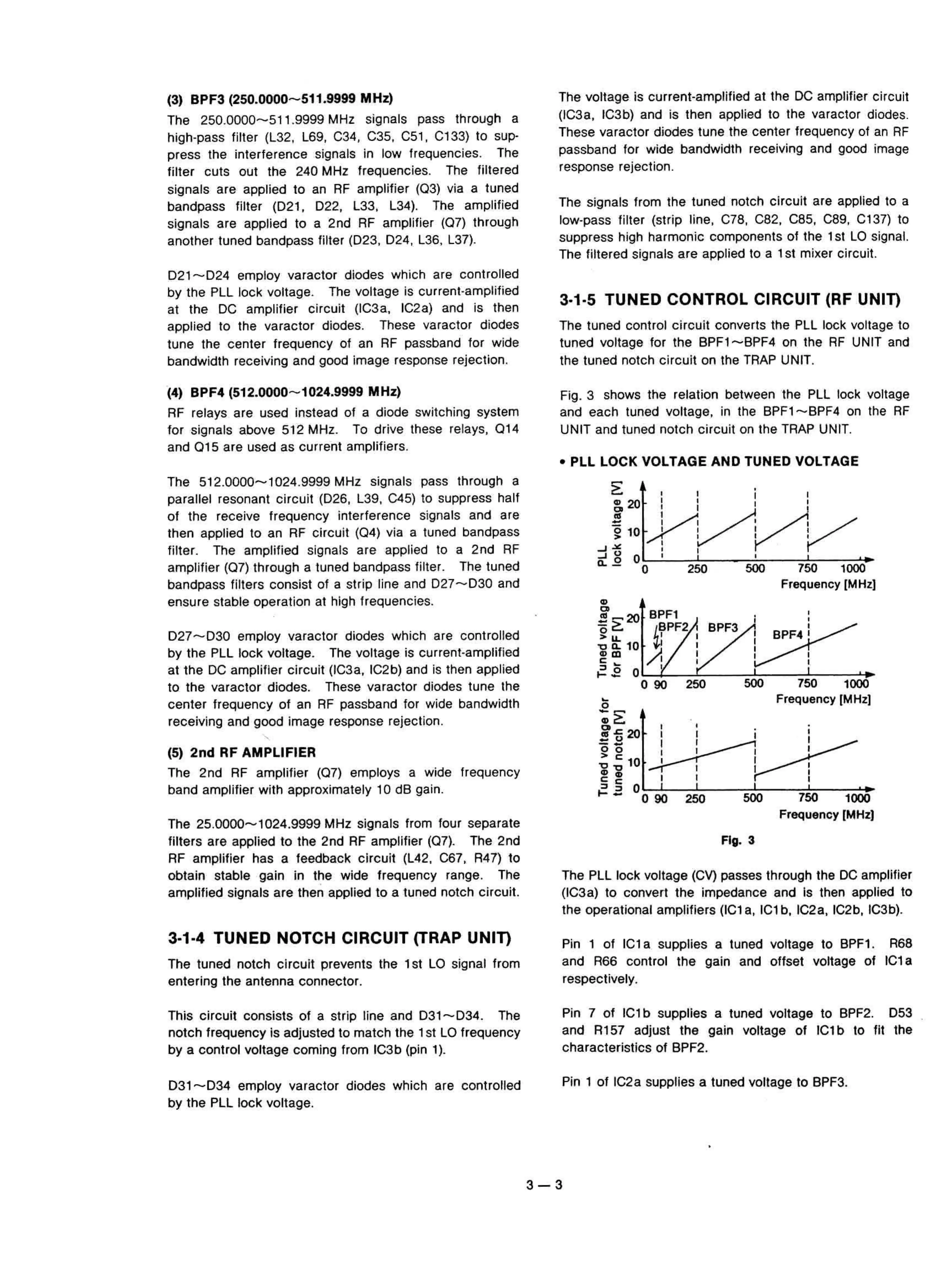
Fig. 3 shows the relation between the PLL loek voltage
and each tuned voltage. in the
BPF1
-BPF4
on the RF
UNIT and tuned notch
circu
it on the TRAP UNIT.
• PLL
LOeK
VOLTAGE AND TUNED VOLTAGE
D27
-0
30
employ varaetor diodes which are controlled
by the PLL loek voltage. The voltage is eurrent-amplified
at
tne DC amplifier circuit (IC3a, IC2b) and is then applied
to the varactor diodes. These varactor diodes tune the
center frequeney
of
an RF passband for wide bandwidth
reeeiving and good image response re
je
ction.
(5)
2nd
RF AMPLIFIER
The 2nd RF amplifier (0 7) employs a wide frequency
band amplifier with approximately 10 dB gain.
The 25.0000
-1024
.9999 MHz signaIs from tour separate
filters are applied to the 2nd RF amplifier
(07
). The 2nd
RF amplifier has a feedback
cir
cu
it (L42, C67, R47) to
obtain stable gain in the wide frequency range. The
amplified signaIs are then applied
10 a tuned notch circuit.
3·1·4 TUNED NOTCH CIRCUIT (TRAP
UNIn
The
luned
notch
circu
il
prevents the 1st
Lü
signal from
enlering the antenna connector.
This circuit consists
of
a strip !ine and 031
-034
. The
noten frequency is adjusted to mateh the 1st
Lü
frequency
by
a control voltage coming from IC
3b
(pin
1)
.
D31--D
34 employ varaeter diodes which are eontrolled
by the PLL lock voltage.
The PLL lock voltage
(CV)
passes through the DC amplifier
(IC3a) to convert the impedance and Is then applied to
the operational amplifiers (ICl a, ICI
b, IC2a, IC2b, IC3b).
Pin 1
of
ICI a supplies a tuned voltage to
BPF1
. R68
and R66 control the gain and offset voltage
of
ICl a
respeetively.
Pin 7
of
IC1b supplles a tuned voitage to BPF2. D53
and R157 adjust the gain voltage
of
tCI b to fit the
characteristl
cs
of BPF2.
Pin 1
of
IC2a supplies a tuned voltage to BPF3.
•
3-3