3·1·27 TIMER CONTROL CIRCUIT
(MAJN UNIT)
013
controts a relay
circuil
(RL2) for Ihe timer function.
The CPU (ICS, pin 34) on
Ihe
LOGIC UNIT outputs a
"HIGH"
signal
w~en
the [TIMER] switch is pushed
OUT. The " HIGH" signaI is applied
10
013
through
Ihe
" POC" line and
lurns
RL2" ON.
3·1
·28 REGULATOR CIRCUIT (MAIN UNIT)
ICtO
is
a voltage
regu
lator prov
id
ing
a sla
bj
e 9 V
10
tne
MAIN and RF UNITs.
3·2
PLL
CIRCUITS
3·2
-1
GENERAL
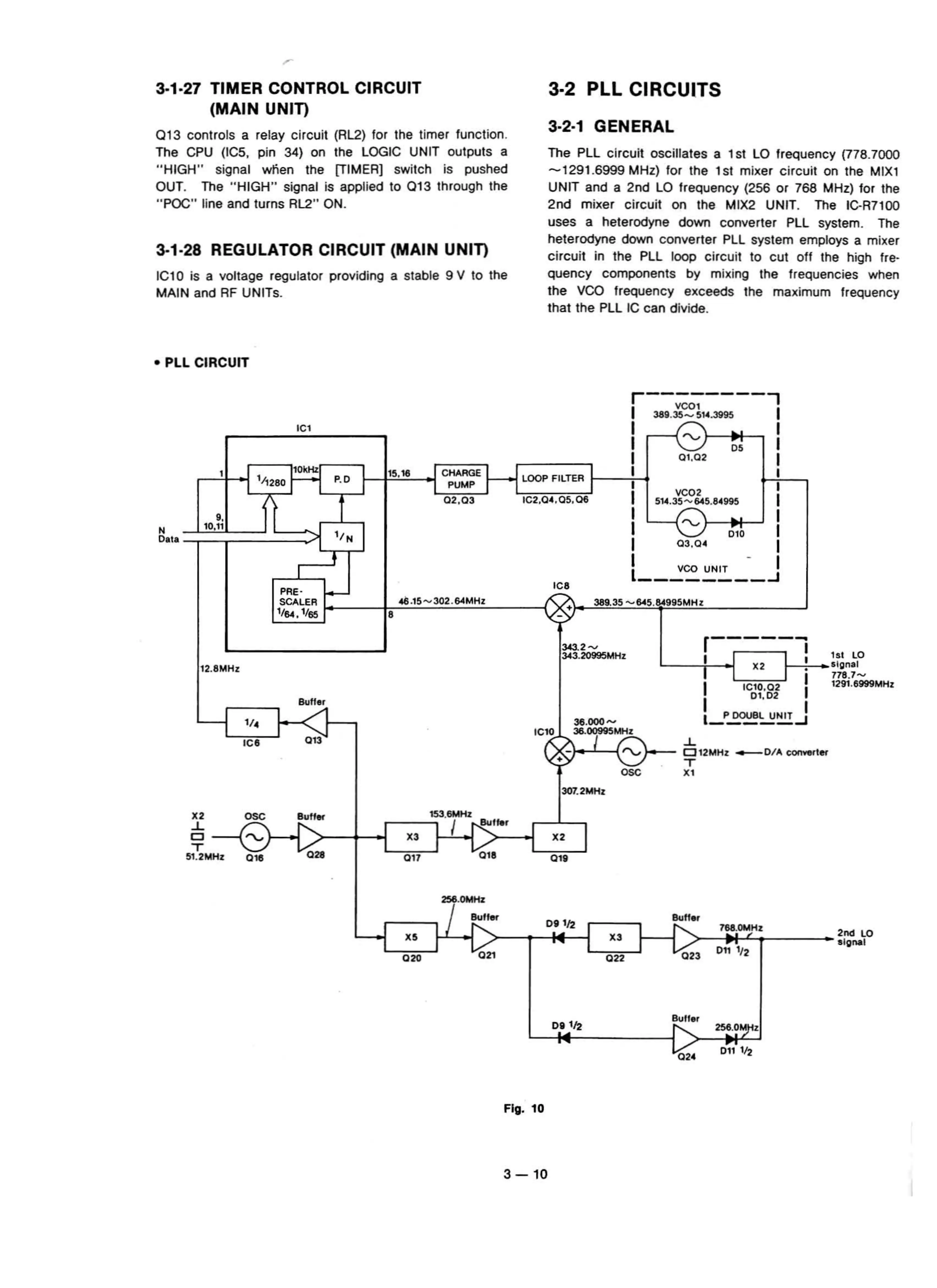
The PLL circuit oscillales a 1st LO frequency (778.7000
-1291
.6999 MHz) tor
Ihe
lsl
mixer
circuil
on Ihe MIX1
UNIT and a 2nd LO frequency (2S6 or 768 MHz) tor Ihe
2nd
mi
xer c
ircuil
on Ihe MIX2 UNIT. The IC-R7100
uses a helerodyne down
conv
erter PLL system.
The
heterodyne
down
converter
PLL
system employs a mixer
circuit
in
Ihe
PLL
loop circu
it
to cut oft Ihe h
igh
tre-
quency components
by
mix
ing
Ihe frequencies when
the VCO frequency exceeds Ihe maximum frequency
that
the PLL IC can divide.
• PLL
CIRCUIT
389.35
-645
.84995MHz
I
C6
r---------,
I
v
coi
389.35_
514
.3995 I
1 I , I
1
v-
05
I
I
01
,02
1
15,16 CHARGE
I-
-l
LOOP FILTER
1--
...,
1
,...,
H
1--,
PUMP
I I
I
VCQ2
02,03
IC2.0 ",OS.
06
514
.35
-645
.84995 I
I
""
I
I
DW
I
I
03
.0'
I
I VCO UNIT - I
1
...J
P.o
" N
•
I
C'
10kHz
I
PRE-
SCA
LEA
I-
__
~~~
:=;
~==
~
1164.1/65
"
10.n
ose
3<3.2
~
J.43
.20995
MHz
12
.8MHz
11
.
IC6
IC10
r-----j
L
_ -
-f
I-
01
I
I X2 i
I
IC10,02
I
I
01
,02
36
.000-
1~
~
~
~J
36..'MHZ
...1..
• -
(
"'~
-
-
~
1
2
M
H
Z.
DIA COl1YeI'tet'
xr
151
ro
!S
lgnal
178
.7
.....
1291
.6999MHz
307
.2MHz
X3
017
ose
""
016
r-
__
.::;'53
.8MHZ
I
I"!!:"lo'
V
010
X2
01'
X5
0
20
768
.tltr.lHI.
X3
022
Fig. 10
3
-10