3·3 LOGIC CIRCUITS
3·3·4 BAND SELECTION DATA (LOGIC
UN
I
The LOGIC
circuit
consists
ol
a one
ch
ip
a-bit CPU (ICS),
an
1/0
expander
(1C4
) controlling the input level l rom
tne
key
matri
x, a 84 k-bit CMOS RAM
(ICll)
and a CI·Y circuit.
The 64 k·bi\
CM05
RAM
(ICll)
contains 900 memory
channe
ls
which can ba div
id
ed
in
to 9 ba
nks
an
d 20 inde-
pendent. pr
ogr
am channels. The CI·V ci
rcuit
contro
ts
frequency,
mode
, memory channels etc..
by
connecling
the receiver with an optional CT·17 CI·Y LEVEL CON·
YERTER
to
a personal
computer
equipped with an
RS·232C port.
3·3·1 RESET CIRCU
IT
(LOGIC UNIT)
The reset
circuit
resets the CPU (ICS), the LCD
driv
er
s
(1C8,
IC9) and the
1/0
expander
(1C4)
when the three-
terminal voltage regulator (IC13) dete
ct
s S V and outputs
S Y. The leading edge voltage is applied
to
a
time
con-
sta
nt
(R24, C22). The " LO
W"
pulse-type signal is
output
trom
the
time
cons
tant
dur
i
ng
Ihe delay time.
The s
ign
al Is inverted at
06
and
is Ihen applied to a
Sch
mi
tl
trigger circuit (IC7) to tune the pulse-type signaI.
The reset signal is applied to the reset ports ol the CPU
(I
CS)
, the LCD driv
er
s (ICa, IC9) and the
1/0
expand
er
(1C4
). 0 14 discharges the voltage of C22.
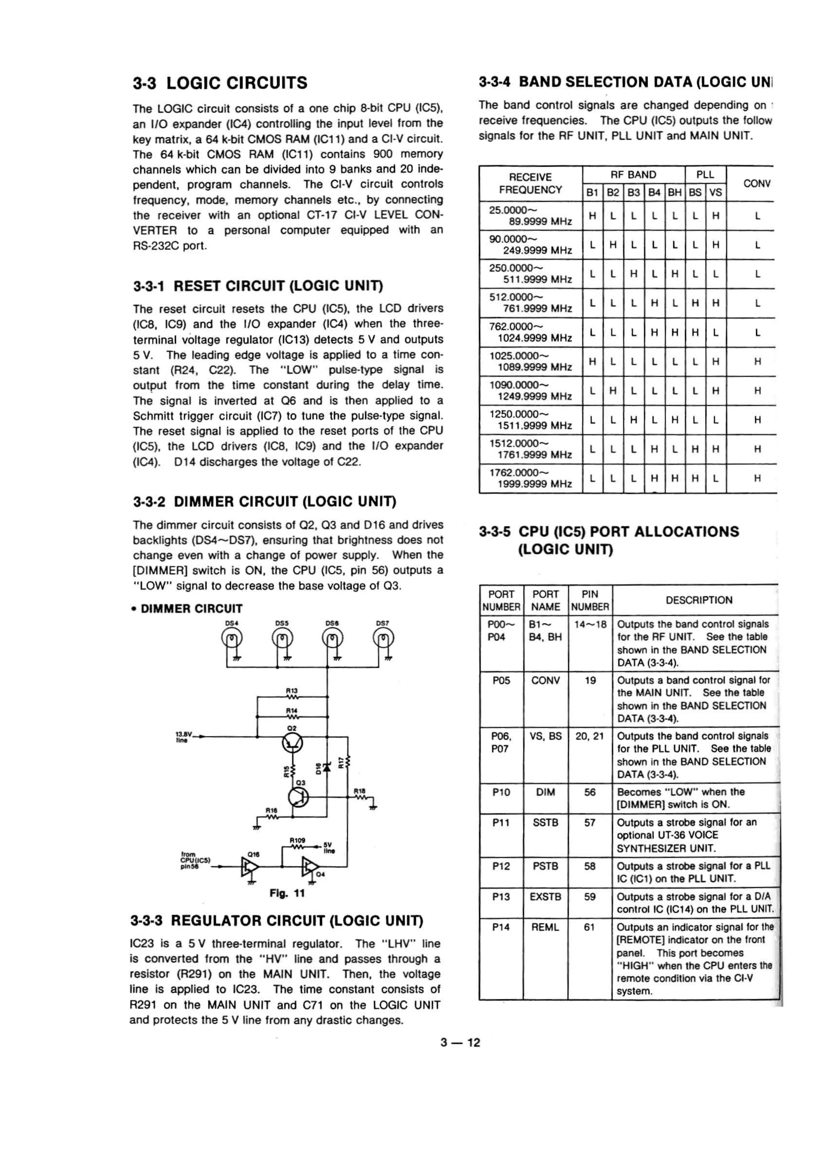
3·3·2 DIMMER CIRCUIT (LOGIC UNIT)
The band control signaIs are changed depending
on
.
receive
treq
uencies. The CPU (IC
S)
outputs the lollow
signals for the RF UNIT, PLL UNIT and MAIN UNIT.
R
EC
E
IV
E
RF B
AN
D
PLL
FREQU
ENCY
CON
V
Bl
B2
B3
84
BH
SS
VS
25.0000-
H L L L L L
H
L
89.9999
MHz
90.0000-
L
H L L L L H
L
249.9999
MHz
250
.0000-
L L H L H L L L
511.9999 MHz
512.
0000-
L L L H L H H L
761
.
9999
MHz
762.0000-
L
L
L H
H
H L L
1024.9999
MHz
1025
.0000-
H L L L L L H H
1089.9999
MHz
1090
.0000-
L H L L L L H H
1249
.9999
MHz
1250
.0000-
L L H L H L L H
1511.9999 MHz
1512
.
0000-
L L L H L H H H
1761
.9999
MHz
1762
.0000-
L L L H
H
H L
H
1999.9999 MHz
Ths dimmer circu
it
cons
ists
of
02
.
03
and 0 16
and
drives
ba
cklights (0
54
- 0 57), ensuring tnat brightness does
not
change even w
ith
a change of
pow
er s
uppl
y.
When
tne
[DIMMER] swi
tc
h is ON, the CPU (
ICS,
pin 56)
outp
ut
s a
" LOW" signal
to
decr
ease the base voltage
of
03
.
•
DIMMER
CIRCUIT
3·3·3 REGULATOR CIRCUIT (LOGIC UNIT)
IC23 is a S Y three-terminal regulat
or
. The
"LHV"
line
is
converted trom me "HV"
li
ne and pa
ss
es through a
resi
stor
(
R29l)
on the MAIN UNIT. Then, the voltage
li
ne
is
applied to IC23. The
time
const
ant
consists
of
R
29l
on the MAIN
UNIT
and C
7l
on the LOGIC UNIT
and pro
tsc
ts Ihe 5 V line trom any drastic changes.
3·3·S CPU
(I
CS) PORT ALLOCATJONS
(LOGIC UNIT)
PORT
PO
RT
PIN
DES
CRIPTION
NUIoABER
NAME
NUIoABER
POO-
B
'l
-r-
1
4-
18
Ou
t
pu
ts the
ba
nd
con
tr
ol
si
gnals
P04
84
,
BH
for the
RF
UN
IT.
See the
table
sh
own
In
th
e
BAND
SELECTlON
DA
TA
(3
-3-
4)
.
P05
CONV
19
Output
s a
ban
d
cont
rol
signal
fo
r
the
MAIN
UNIT. See the tabla
sho
wn
in
the
BAND
SELECTl
ON
DATA
(3-
3-4
).
POS.
VS,
SS
20
, 21
Outpu
ts
the
ba
nd c
ontr
ol
signa
ls
,
P
07
lor
th
e
PLL
U
NIT
. See
th
e tabla
shown
in
the
BAND
SEL
EC
TION
DATA
(3
'3-4)
.
PlO D
IM
56
Be
comes
·
·LOW
"
when
the
(D
IMM
ER]
switch is
ON
.
Pl l SS
TB
57
Out
pu
ts
a strobe s
ig
nal t
or
an
optiona
l UT·36
VO
IC
E
SYNTH
ES
IZE
R
UN
IT
.
P12
PSTB
SB
Outpu
ts
a
strobe
s
ignal
lor a PLl
IC
(IC1
) on
the
PL
L
UN
IT.
P13
EXSTB
59
Outputs
a st
rot>e
s
ig
nal lor a D
IA
contro
l
IC
(
IC14
) on
th
e PLL U
NI
T.
P
14
REML
61
Output
s an
indicato
r s
lg
nal
tor
I
hs
(AEMOTE]
indicator
on
the
Ironl
panel.
Th
is
pon
be
comes
"HIGH"
when
the CPU e
nters
1
he
remale
conditi
on
via the CIN
system
.
•
DS
'
DS
'
FIg.
11
".
(
{
(
'"'IJ
I)
RU
RU
••
f
,
•
e
•
•
•
0
••
Ru
Ru
r
'
J.
J.
R
'"
"
...
,
...
UC
3l
..
DO
3-
12