4 - 1
SECTION 4 ADJUSTMENT PROCEDURE
¤ REQUIRED TEST EQUIPMENTS
EQUIPMENT GRADE AND RANGE EQUIPMENT GRADE AND RANGE
DC voltmeter Input impedance : 50 k
Ω
/V DC or better
Standard signal
generator (SG)
Frequency range : 0.1–3.5 GHz
Output level : 0.1 µV to 32 mV
(–127 to –17 dBm)
Output impedance : 50
Ω
Modulation : None
RF Milliwatt meter
Measuring range : 0.5–5 dBm
Input impedance : 50
Ω
Frequency counter
Frequency range : 0.1–300 MHz
Frequency accuracy : ±1 ppm or better
Sensitivity : 100 mV or better
AC millivoltmeter Measuring range : 10 mV to 10 V
External speaker
Input impedance : 8
Ω
Capacity : More than 5 W
4-1 PREPARATION
¤ CONNECTION
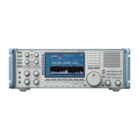
IC-R9500
AC millivolt meter
Speaker (8 Ω)
(Short)
• Short plug
S
hort pl
ug
Ex
ter
nal speaker pl
ug
F
re
q.
Co
un
ter
3.5 mm (1/8’’ ) monoral plug
3.5 mm (1/8’’ ) monoral plug
• External speaker plug
SG (for adjustment [HF] )
SG (for adjustments [V/U], [V/U1], [TV] and [WFM])
SG (for adjustment [V/U2])
+
−
+
−
¤
ENTERING ADJUSTMENT MODE
q
Connect the short plug (see the iluustlation below) to the [REMOTE] jack.
w
Push and hold [FM] and [WFM] keys then turn the power ON.
e
The main adjustment menu will appear as next page.
 Loading...