4-1
SECTION 4
CIRCUIT DESCRIPTION
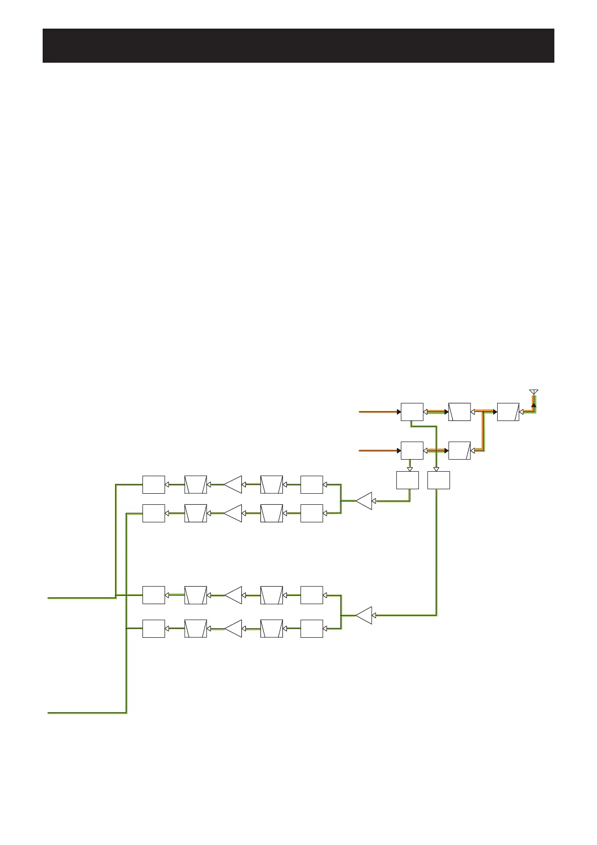
4-1 RECEIVE CIRCUITS
RF CIRCUITS (MAIN UNIT)
VHF BAND (108–174 MHz)
The RF signal from the antenna is passed through two LPFs
(L90, L94, L96, C409, C418 and L79, L83, L87, C378, C386,
C394), ANT SW (D66, D69, D70 and D77), and then applied
to the RF AMP (Q24).
• Band A
The amplifi ed signal is passed through the ATT (D34), BPF
(D28, D88, L24, L26, L31 L34, C127 and C128), and then
applied to another RF AMP (Q20).
The amplifi ed signal is applied to the 1st IF circuit, through
the BPF (D20, D87, L10, L18, C71 and C74) and RX circuit
SW (D14).
• Band B
The amplifi ed signal is passed through the ATT (D33), BPF
(D27, D85, L23, L25, L32, L33, C125 and C126), and then
applied to another RF AMP (Q19).
The amplifi ed signal is applied to the 1st IF circuit, through
the BPF (D19, D86, L9, L17, C69 and C70) and RX circuit
SW (D13).
UHF BAND (380–479 MHz)
The RF signal from the antenna is passed through the LPF
(L90, L94, L96, C409 and C418) and HPF (L84, L88, C391,
C395 and C402) and ANT SW (D68, D73, D75 and D84), and
then applied to the RF AMP (Q23).
• Band A
The amplifi ed signal is passed through the ATT (D32), BPF
(D24, D26, L21, L28, C113 and C114), and then applied to
the RF AMP (Q18).
The amplifi ed signal is applied to the 1st IF circuit, through
the BPF (D12, D16, L4, L12, C42 and C43) and RX circuit
SW (D8).
• Band B
The amplifi ed signal is passed through the ATT (D31), BPF
(D23, D25, L22, L27, C107, C111, C112 and C121), and then
applied to the RF AMP (Q17).
The amplifi ed signal is applied to the 1st IF circuit, through
the BPF (D11, D15, L3, L11, C36, C40, C41 and C49) and
RX circuit SW (D7).
BPF
HPF
RF
AMP
RF
AMP
ATT
TX/RX
SW
BPF
BPF
BPF
ATT
RF
AMP
LPF
BPF
ANTENNA
BPF
RF
AMP
BPF
LPF
RF
AMP
RF
AMP
ATT
TX/RX
SW
BPF
ATT
RX
SW
RX
SW
RX
SW
RX
SW
LIMITER
LIMITER
118-550MHz
118-174MHz
375-550MHz
118-174MHz
VHF BAND
UHF BAND
375-550MHz
Band A
Band A
Band B
Band B
400-470MHz
137-174MHz
1st IF
circuit
1st IF
circuit
D68/D73/D75
D66/D69/
D70/D77
D79D81
Q24
D34D28/D88Q20D20/D87D14
D33D27/D85Q19D19/D86D13
Q23
D32
D22/D24/
D26/D30
Q18
D10/D12/
D16/D18
D8
D31
D21/D23/
D25/D29
Q17
D9/D11/
D15/D17
D7
D84
• RF CIRCUITS

 Loading...


