5-2
ADJUSTMENT ITEM ADJUSTMENT CONDITIONS OPERATION VALUE
REFERENCE
FREQUENCY
(Band A)
[REF] 1 • Connect an RF power meter to the antenna
connector.
• Loosely couple a Frequency Counter to the
antenna connector.
• Transmitting
Rotate Band B [DIAL] to adjust
the transmit frequency, and then
touch [ENT] during transmit.
Displayed
frequency
(±200 Hz)
(Band B) 2
M
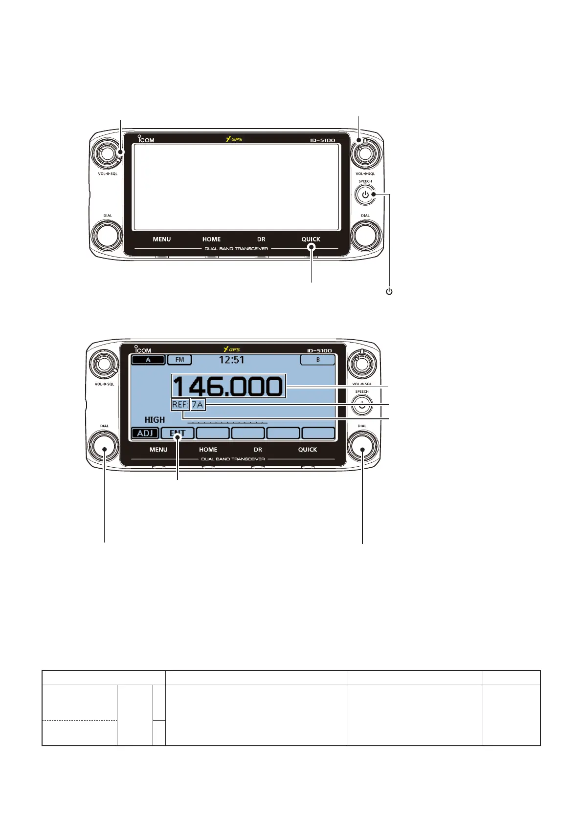
ENTERING THE ADJUSTMENT MODE
1) Connect the JIG cable to the MICROPHONE CONNECTOR (see the illustration on page 5-1).
2) Turn Band A [SQL] maximum clockwise.
3) Set Band B [SQL] to the center position.
4) Touch and hold [QUICK], and turn ON the power.
• Enters to the adjustment mode.
M
A
I
N
B
A
N
D
Band A [DIAL]
Turn Clockwise : Selects the next adjustment item.
Turn Counterclockwise : Selects the previous adjustment item.
Band B [DIAL]
Adjusts the value for the item.
(For the manual adjustments)
Adjustment item name.
Adjustment value.
[ENT]
• Stores the set value.
(For the manual adjustments)
• Adjusts the value for the item.
(For the automatic adjustments)
Adjustment frequency.
4) Touch and hold [QUICK], then push [ ] turn ON the power.
M
A
I
N
B
A
N
D
2) Turn Band A [SQL] maximum clockwise.
3) Set Band B [SQL] to the center position.
M
KEY ASSIGNMENTS IN THE ADJUSTMENT MODE
5-2 FREQUENCY ADJUSTMENT
1) Select the adjustment item by rotating Band A [DIAL].
2) Set or modify the adjustment value as specifi ed by rotating Band B [DIAL].
3) Touch [ENT] to store the value.

 Loading...


