Do you have a question about the Icom PMR446 and is the answer not in the manual?
Critical safety warnings for operating the transceiver.
Information and format for ordering replacement parts.
Important guidelines and precautions for servicing the transceiver.
General specs: channels, frequency, power, operating range.
Specs for transmitter output power and modulation system.
Specs for receiver sensitivity and performance metrics.
Top and bottom views identifying main unit components.
Top and bottom views identifying RF unit components.
Steps to remove the rear panel of the transceiver.
Steps to remove the main unit from the transceiver.
Steps to remove the RF unit from the transceiver.
Detailed description of receiver circuit functions and signal paths.
Explanation of the 2nd mixer and demodulator circuit operations.
Description of the audio frequency circuit path and amplification.
Explanation of noise and tone squelch circuit operations.
Detailed description of transmitter circuit functions and signal flow.
Description of the Phase Locked Loop circuit for frequency stability.
Explanation of different voltage lines used in the device.
Pinout and function allocation for the CPU on the main unit.
List and specifications of necessary test equipment for adjustments.
Diagram and instructions for connecting test equipment.
Procedure for adjusting the reference frequency.
Procedure for adjusting the output power.
Procedure for adjusting the FM deviation.
Procedure for adjusting the squelch circuit.
List of parts for the main unit.
Continuation of the main unit parts list.
Further components for the main unit.
List of components for the RF unit.
Continuation of the RF unit parts list.
Continuation of the RF unit parts list.
List of chassis parts and their quantities.
Items included in the product's unpacking.
Mechanical parts specific to the main unit.
Mechanical parts specific to the RF unit.
Diagrams and symbols for transistors and FETs.
Diagrams and symbols for diodes used in the device.
Top view layout of the main unit's printed circuit board.
Bottom view layout of the main unit's printed circuit board.
Top view layout of the RF unit's printed circuit board.
Bottom view layout of the RF unit's printed circuit board.
Block diagram illustrating the RF unit's functional modules.
Block diagram illustrating the main unit's functional modules.
Voltage distribution diagram for the main unit.
Voltage distribution diagram for the RF unit.
| Brand | Icom |
|---|---|
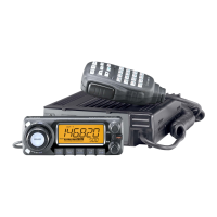
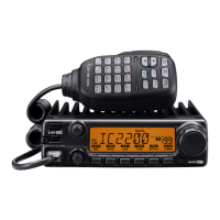
| Model | PMR446 |
| Category | Transceiver |
| Language | English |