BIA-DPC1 rev 4 Page 4
Cont....
TABLE OF CONTENTS cont.
4.0 INSTALLATION – TRANSFER
4.1 Electrical connection to the power supply and pump 27
4.2 Function switch setting 28
4.3 Connections for pump over temperature protection (where supplied) 29
4.4 Installing float switches and probes 29
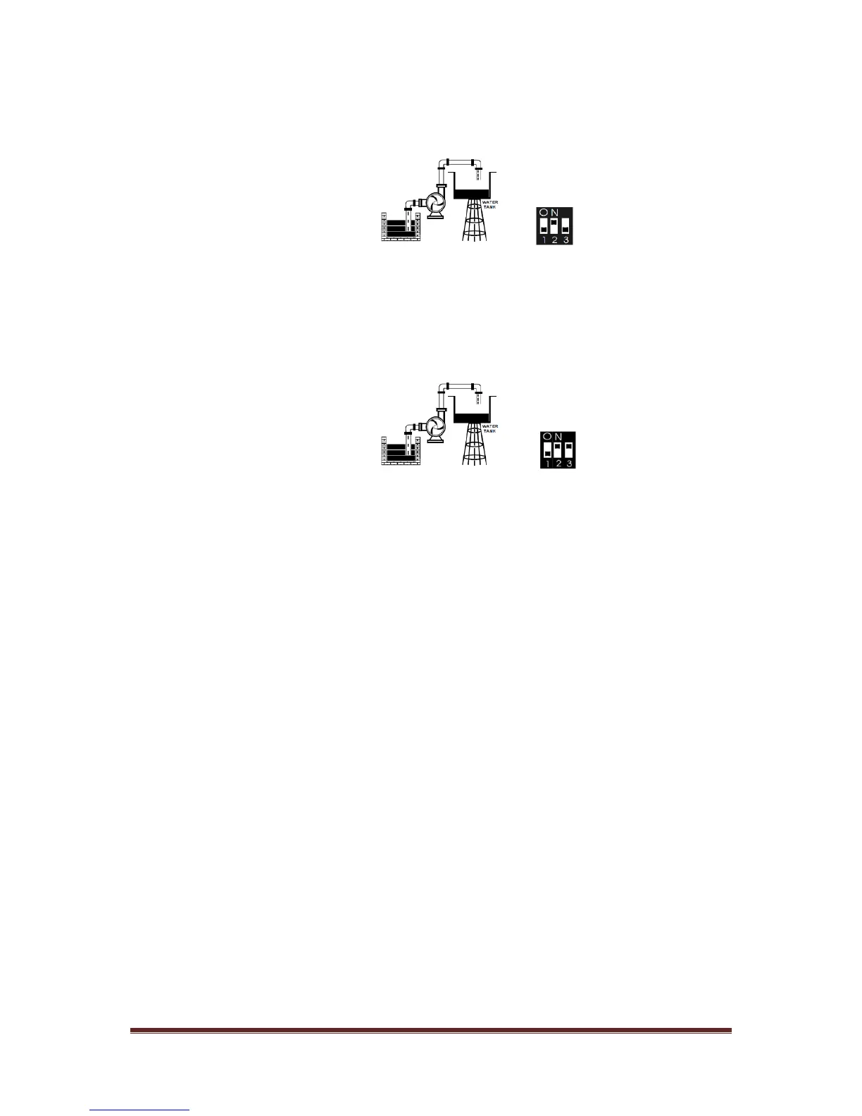
4.5 Diagrams for transfer by liquid level through float switches or probes 30
4.0a INSTALLATION – TRANSFER
HOT WATER CIRCULATION
4.1a Electrical connection to the power supply and pump 33
4.2a Function switch setting 34
4.3a Connections for pump over temperature protection (where supplied) 35
4.4a Installing float switches and probes 35
4.5a Diagrams for transfer by liquid level through float switches or probes 36
5.0 OPERATION
5.1 BEFORE YOU START – Parameter calibration and erasing 37
5.2 Switching to AUTO mode 38
5.3 Switching to MANUAL mode 38
5.4 Alarm Test and MUTE 38
5.5 Pump protection 38
5.6 Last five failure record 39
5.7 Pump accumulated running time 39
5.8 Pump disable 39
6.0 COMMUNICATION LINK 40
6.1 Basic Function 41
6.2 Special application 41
6.3 Technical parameters 41
7.0 TROUBLE SHOOTING GUIDE 42