BIA-DPC1 rev 4 Page 3
TABLE OF CONTENTS
Page
1.0 INTRODUCTION
1.1 Applications 5
1.2 Technical parameters and features 5
1.3 Meanings of the icons shown on the LCD 7
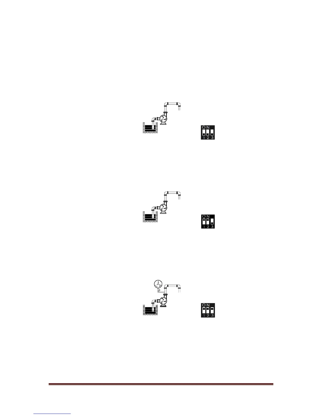
2.0 INSTALLATION – DRAINAGE
2.1 Electrical connection to the power supply and pump 8
2.2 Function switch setting 9
2.3 Connections for pump over temperature protection (where supplied) 10
2.4 Installing float switches and probes 10
2.5 Diagrams for drainage by liquid level through float switches or probes 11
2.0a INSTALLATION – DRAINAGE
WITH AUTOMATIC PUMPS
2.1a Electrical connection to the power supply and pump 15
2.2a Function switch setting 16
2.3a Connections for pump over temperature protection (where supplied) 17
2.4a Installing float switches and probes 17
2.5a Diagram for drainage by liquid level 18
3.0 INSTALLATION – BOOSTING
3.1 Electrical connection to the power supply and pump 20
3.2 Function switch setting 21
3.3 Connections for pump over temperature protection (where supplied) 22
3.4 Installing float switches and probes 22
3.5 Diagrams for boosting by liquid level through float switches or probes 23