9
7
72
A
78
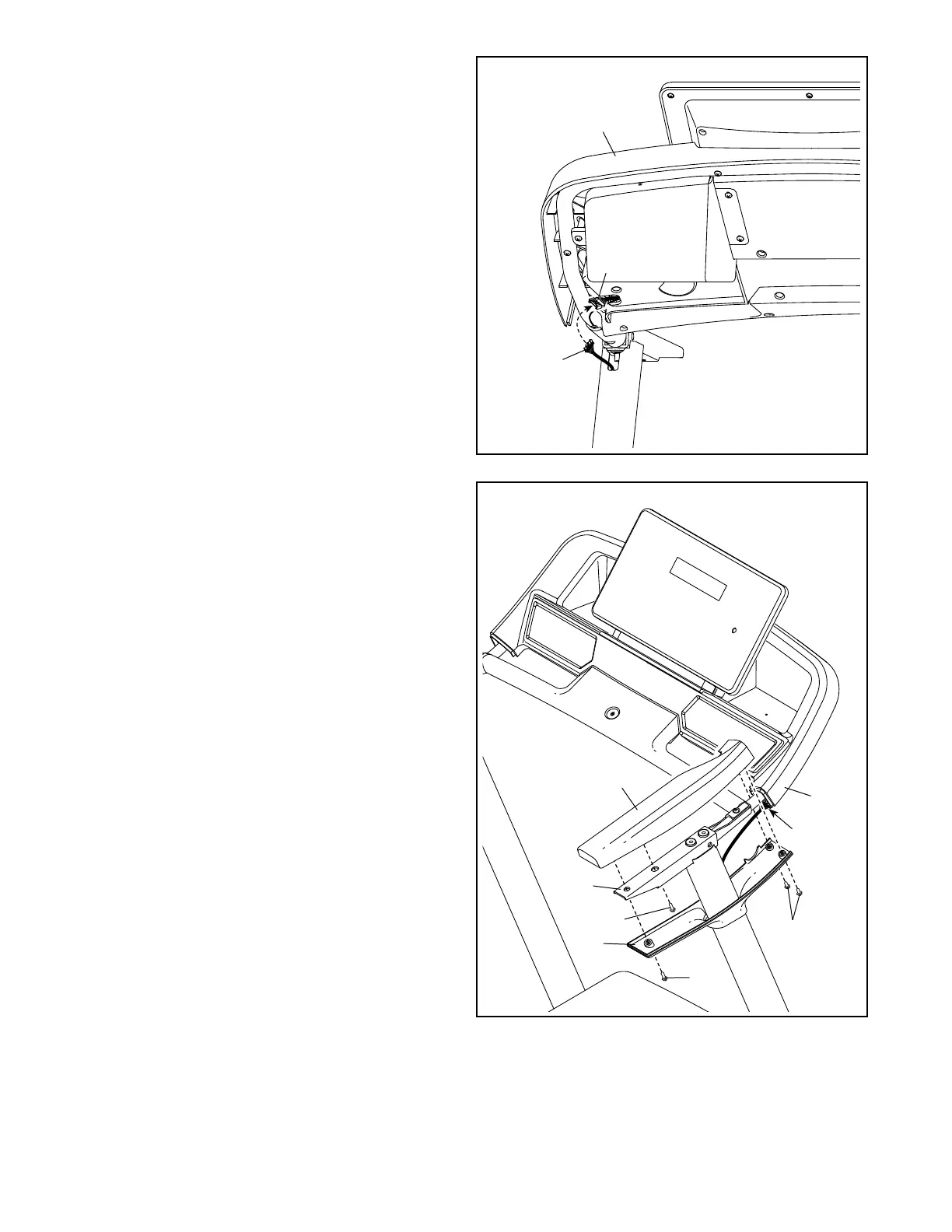
7. Identify the Right Handrail Top (72). Set the
Right Handrail Top on the Handrail (76), and
slide it forward against the console assembly
(A). Attach the Right Handrail Top with a #8 x
3/4" Screw (29). Note: The Screw must be
inserted at an angle as shown. Be careful not
to overtighten the Screw.
Next, slide the Right Handrail Bottom (74)
upward. Make sure that the Upright Wire (78)
is covered by the Right Handrail Bottom
and is not pinched. Attach the Right Handrail
Bottom with three #8 x 3/4” Screws (29). Note:
The Screws must be inserted at an angle
as shown. Be careful not to overtighten the
Screws.
Attach the Left Handrail Top (not shown)
and the Left Handrail Bottom (not shown) as
described above. Note: There are no wires on
the left side.
76
74
6. Connect the Upright Wire (78) to the con-
sole wire (B). The connectors should slide
together easily and snap into place. If they do
not, turn one connector and try again.
Insert any excess wire into the console
assembly (A).
6
B
A
78
29
29
29
 Loading...