SERVICE AND TECHNICAL SUPPORT MANUAL Gas Furnace: (F/G)9MVE
Specifications subject to change without notice.
18 440 04 4801 03
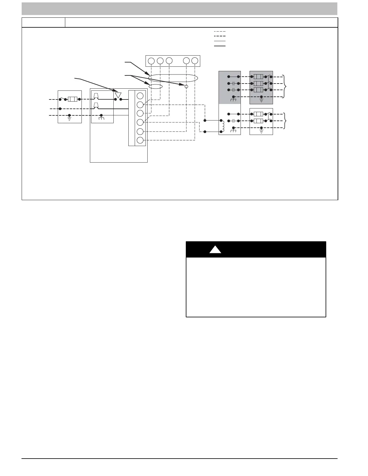
Figure 8 Heating and Cooling Application Wiring Diagram with Single−Stage Thermostat
A11401
115-VOLT FIELD-
SUPPLIED
FUSED
DISCONNECT
JUNCTION
BOX
24-VOLT
TERMINAL
BLOCK
THREE-WIRE
HEATING-
ONLY
FIVE
WIRE
NOTE 2
NOTE 1
1-STAGE
THERMOSTAT
TERMINALS
FIELD-SUPPLIED
FUSED DISCONNECT
CONDENSING
UNIT
FURNACE
COM
R
WC Y RG
GND
GND
FIELD 24-VOLT WIRING
FIELD 115-, 208/230-, 460-VOLT WIRING
FACTORY 24-VOLT WIRING
FACTORY 115-VOLT WIRING
Connect Y/Y2-terminal as shown for proper operation.
Some thermostats require a "C" terminal connection as shown.
If any of the original wire, as supplied, must be replaced, use
same type or equivalent wire.
208/230- OR
460-VOLT
THREE
PHASE
208/230-
VOLT
SINGLE
PHASE
WHT
BLK
WHT
BLK
W/W1
W2
Y/Y2
G
NOTES: 1.
2.
3.
BLOWER
DOOR
SWITCH
C
O
N
T
R
O
L
For an explanation of status codes, refer to service label
located on control door or Figure 15, and the troubleshooting
guide which can be obtained from your distributor.
Retrieving Stored Fault Codes
The stored status codes will NOT be erased from the control
memory, when 115− or 24−v power is interrupted. The control
will store up to the last 7 Status Codes in order of occurrence.
1. To retrieve status codes, proceed with the following:
NOTE: NO thermostat signal may be present at control, and all
blower−OFF delays must be completed.
a. Leave 115−v power to furnace turned on.
b. Look into blower door indicator for current LED
status.
c. Remove blower door.
NOTE: The Status Codes cannot be retrieved by
disconnecting the limit switch. To retrieve Status Codes, follow
the procedure below.
2. Turn Setup Switch, SW1−1 “ON.”
3. Manually close blower door switch.
4. Control will flash up to 7 Status Codes.
5. The last Status Code, or 8th Code, will be a heartbeat.
6. Turn SW1−1 “OFF.”
7. A heartbeat amber LED will appear and indicates proper
operation.
8. Release blower door switch, install control door and
refer to the SERVICE label on the control door for more
information.
Component Self−Test
Component Test can ONLY be initiated by performing the
following:
1. Remove blower door.
2. Remove the wire from the “R” terminal of the control
board.
3. Turn Setup Switch, SW−1−6 “ON.”
4. Manually close blower door switch.
Blower door switch opens 115−v power to control. No
component operation can occur unless switch is closed.
Caution must be taken when manually closing this switch for
service purposes.
ELECTRICAL SHOCK HAZARD
Failure to follow this warning could result in personal
injury, or death.
Blower door switch opens 115−v power to furnace
control. No component operation can occur unless
switch is closed. Exercise caution to avoid electrical
shock from exposed electrical components when
manually closing this switch for service purposes.
!
WARNING
5. Component Test sequence will function as follows:
a. Inducer motor starts on high−speed and continues to
run until Step (d.) of component test sequence.
b. Hot surface igniter is ON for 15 sec, then OFF.
c. Blower operates for 15 sec, then turns off.
d. Inducer motor goes to low−speed for 10 seconds,
then turns off.
e. After component test is completed, one or more
status codes (heartbeat, 2+5) will flash. See
component test section of service label for
explanation of status codes.
NOTE: To repeat component test, turn setup switch SW1−6
OFF then back ON.
f. Turn setup switch SW1−6 OFF.
 Loading...