Exit Reader Connections
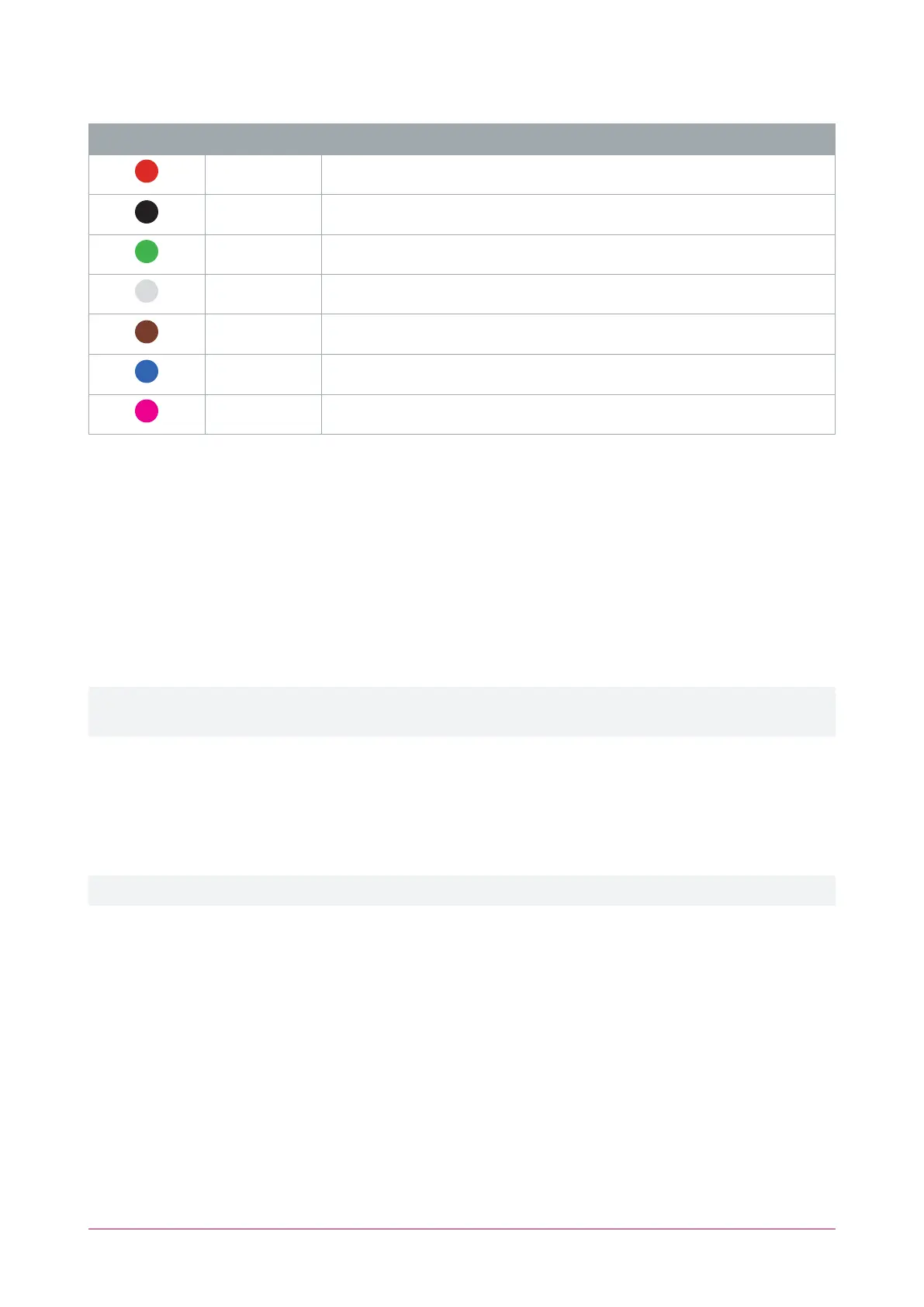
Color Wire Connection
Red Join to entry reader red wire ( 12VDC positive)
Black Join to entry reader black wire ( 12VDC negative)
Green Join to entry reader green wire (Wiegand Data 0)
White D1/NB Wiegand Data 1 (alternate reader port to entry reader)
Brown Join to entry reader brown wire (LEDcontrol)
Blue Join to entry reader blue wire (beeper control)
Shield Join the shield (drain) wires together. Frame grounded at one point only
Connecting 4 Wiegand Readers
Multiple reader mode allows the connection of 4 Wiegand readers controlling 2 doors, each with entry/exit
readers. To connect 4 Wiegand reading devices to a Protege module:
⦁ Door 1 entry reader is connected to reader port 1
⦁ Door 1 exit reader has its Wiegand Data 1 wire connected to the reader port 2 D1 connection
⦁ Door 2 entry reader is connected to reader port 2
⦁ Door 2 exit reader has its Wiegand Data 1 wire connected to the reader port 1 D1 connection
⦁ The Multiple reader input port 1 option is enabled in the reader expander programming (General | Options)
⦁ The Multiple reader input port 2 option is enabled in the reader expander programming (General | Options)
To connect two Wiegand readers to a reader port the Multiple reader input port 1/2 option must be enabled in
the reader expander programming. When this option is disabled the reader port will only process a single reader.
Enabling Wiegand Mode
TSL readers are shipped in RS-485 configuration by default. To change a reader to Wiegand mode it must be
enabled using a mobile device running the Protege Config App. The ConfigApp's Reader Configuration will need
a config with the Output Mode set to Wiegand Output.
For programming instructions, see the ICT Card Reader Configuration Guide, available from the ICT website.
TSL Multi-Technology Card Reader | Installation Manual 29