5.7 Mounting valve-box into a timber stud wall
These products can be installed into a modern timber stud construction partition wall.
The mounting bracket supplied (option B) can be attached to any side of the valve-box (see 4.3 & 5.2). This
enables the valve-box to be secured to either a timber stud (vertical on either side) or to a timber noggin
(horizontal, below or above the valve-box).
Mounting bracket can be secured from in-front of the wall or from behind.
Alternatively, the valve-box can also be mounted directly using the corner slots.
For retrot t applications, an area of plaster board approximately 400x400 should be cut away and then
replaced after installation. This is necessary to facilitate pipe connections. The framework may need to be
adjusted to provide a means of fastening and supporting the product.
TIMBER STUD WALL framework is normally constructed using 75x50 (3”x2”) rough sawn timbers, for larger
walls 100x50 (4”x2”) can be used. Stud centres spacing of 400 is used here in discussion. Note that 450 and
600 centres are also commonly used - this usually dependents on the plaster board size being used. Plaster
board thickness of 12.5 (1/2”) is generally recommended.
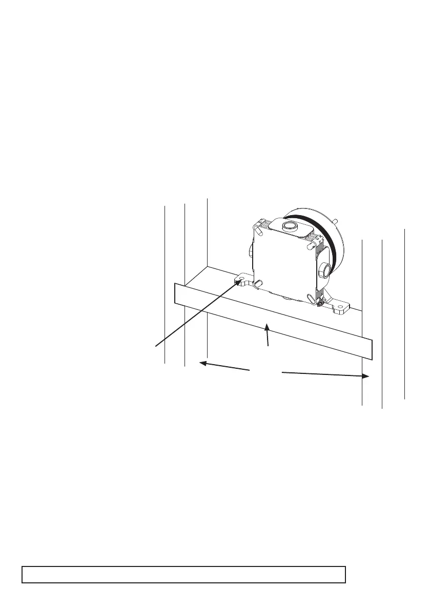
Rear view showing valve-box being
mounted to a noggin below.
Framework illustrated here uses
75x50 timbers on 400 centres.
(Wall cavity = 75mm).
Remember to make an allowance in
framework for connecting pipes
Fit a horizontal noggin into the framework at the desired
mounting location for the valve-box. The bottom surface of
the bracket is 75mm from the centre of the valve-box. Therefore, the top
edge of the noggin should be positioned 75mm below the desired valve-box
centre. Ensure noggin is level & secured.
Installation of valve-box will be easier if the front plaster board is fastened to the timber framework, but don’t
fasten the rear plasterboard until the installation is completed. Cut a large hole in the front plasterboard (see
5.4) at the desired location for the valve-box. Note: Before mounting, it may be easier to t pipe connectors
to the valve-box (see 5.1).
Guide the valve-box into the large hole until it stops against the back of the plasterboard. The mounting
bracket should be sitting on the noggin. Check level & valve-box orientation (see 4.5). Conrm valve-box is
projecting from the front of the plasterboard correctly; such that the nished wall will fall between the depth
markers (see 4.2). The valve-box can be slid along the noggin until this depth is achieved.
Fit two suitable wood screws through the bracket into the noggin to secure.
Using this method the min’ wall cavity depth can be as little as 45mm.
Studs
Noggin
2 holes for xing
srews
21
 Loading...