38
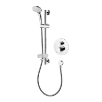
12 Flow cartridge replacement
To replace the ow control cartridge, ISOLATE WATER SUPPLIES FIRST.
Drain down the pipe work as much as possible.
1. Undo the grub screw that secures the handle.
2. Pull off the ow control handle & this will expose the cartridge spindle.
3. Pull off the ow control shroud. A brass ring supports the shroud, pull this brass ring off too. It is retained
on the ow control valve using a snap clip. This will expose the remainder of the ow control cartridge.
The brass ring should have an o-ring tted on the outside & a snap ring on the inside.
4. Unscrew cartridge with a 17mm A/F deep socket, expect some trapped water to escape. Replace the
cartridge if necessary. When retting cartridge, do not over tighten, hand tighten the rst few threads,
maximum torque 12Nm.
5. The black drive spindle (sleeve) should be retted to the new cartridge.
ENSURE PARTS ARE REASSEMBLED IN THE CORRECT SEQUENCE.
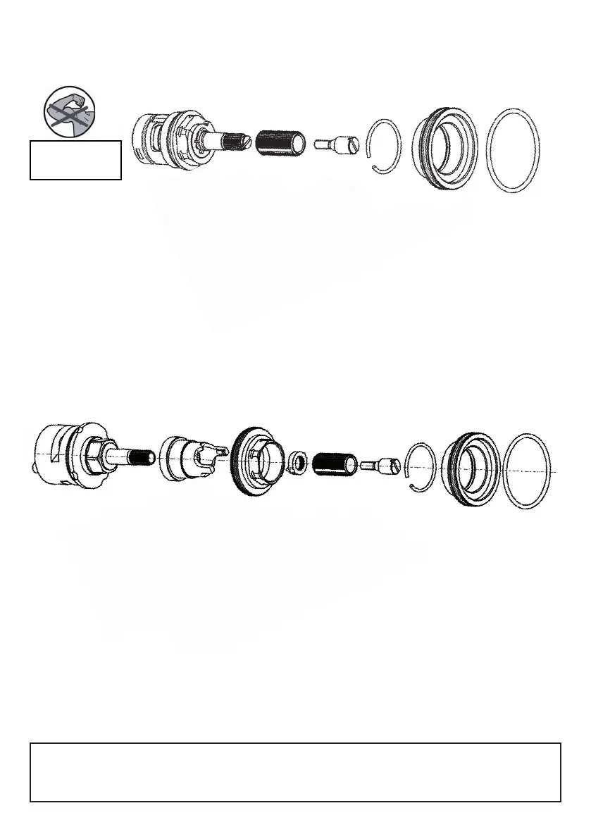
13 Diverter cartridge replacement
To replace the diverter cartridge, ISOLATE WATER SUPPLIES FIRST.
To drain off some off the water inside the valve-box, turn diverter handle to tub ll.
1. Undo the grub screw that secures the handle.
2. Pull off the diverter handle & this will expose the cartridge spindle, see 6.3.
3. Pull off the diverter shroud. A brass ring supports the shroud, pull this brass ring off too. It is retained on
the diverter clamping bush using a snap clip. The brass ring should have an o-ring tted on the outside &
a snap ring on the inside. This will expose some of the diverter cartridge.
4. Unscrew the diverter clamping bush with a 22mm A/F deep socket. This will release the plastic positional
moulding & the diverter cartridge. Expect some trapped water to escape. Replace the diverter if
necessary.
5. The black drive spindle & positional sleeve should be retted to the new cartridge (undo the screw tted
to the spindle).
ENSURE PARTS ARE REASSEMBLED IN THE CORRECT SEQUENCE.
See next page for set-by-step re-assembly information.
Refer to 6.3 for assembling handle.
NOTE: If the outlet pipes from the valve-box have been reversed during installation,
this problem can be solved (in other words the tub ll connection has been made to the top of the valve-
box). Remove the diverter cartridge as detailed above, then rotate it 180° & ret. The cartridge lug will t
into the secondary hole (D) shown on the next page.
 Loading...