6.0 Preparation for chrome trim (kit-2)
Once the valve-box installation has been completed, & the wall is in a nished state
(either tiled or panel nish) the plaster guard can be removed & valve-box must be trimmed as detailed
below.
NOTES:
• It is important to use the eece mat supplied to seal the wall around the valve-box
if wall is being tiling (see 4.6 & 4.7).
• Wall tiles should be carefully trimmed to match the projecting valve-box diameter.
• Removal of trim kit will permit access to the valve cartridges for future maintenance.
To do this, just reverse the following installation sequence.
Pull of plasterguard
Illustrated above, valve-box projecting from the nished wall at the correct depth.
The plaster guard can now be removed to expose the valve assembly inside.
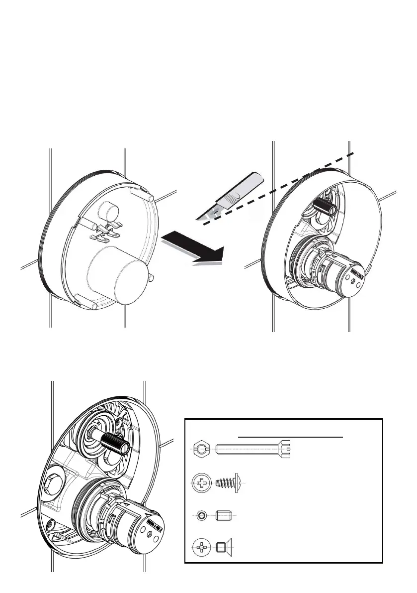
Use a sharp craft knife to carefully trim the valve-box diameter. Select a suitable line marked on the diameter
as a trimming guide. The diameter should be trimmed level with the nished wall. Take care not to damage
components inside the valve-box
Illustrated on the left, the valve-box has been correctly
trimmed. In this example, the product is the version with the
integral “ow control”.
The trim kit can now be tted.
Trim kit screw identication
2x Up-stand bolts
1x Temperature handle screw
1x Flow control handle screw
2x Lid xing screws
29
 Loading...