Method B: cont.
Attaching the mounting bracket to either top or bottom of the valve-box permits the product to be secured to
a timber noggin (horizontal) in a partition wall. Alternatively, attach the bracket to either side of the valve-box
to utilise a nearby timber stud (vertical) for xing.
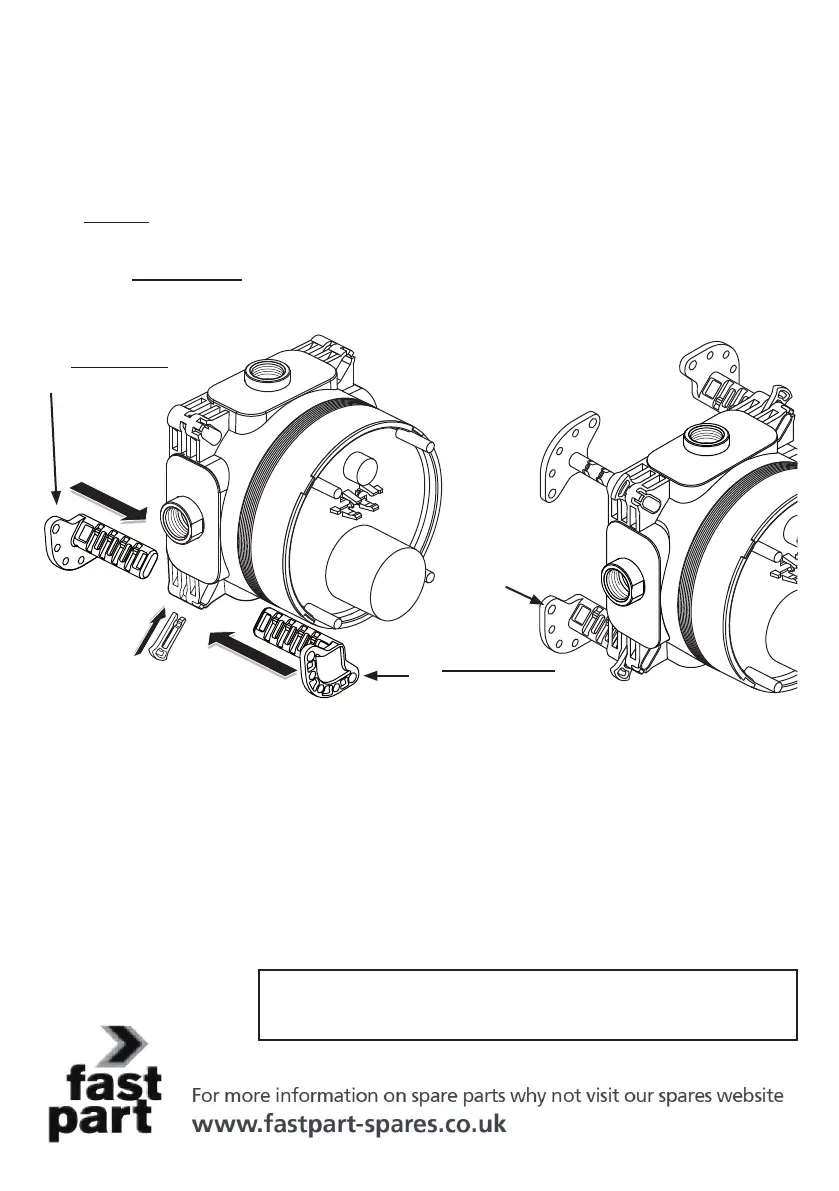
To attach the xing legs to the valve-box:
For a solid wall insert each leg into a slot from the rear. Select a suitable depth by aligning a groove on the
leg to the clip-slot then push the latching clip home until it clicks.
Similarly for panel mounting insert each leg into a slot from the front. Select suitable depth & secure all 4
legs with latching clips.
Note; If further depth adjustment is required, the latching clips can be easily be removed by pulling on the
projecting lobe of the clip. Slide the leg along the slot until a more suitable leg-groove is visible, and then
ret the latching clips to secure.
ADJUSTMENT NOTE: The xing legs have 4 grooves permitting 4 depth settings.
Ensure all 4 legs are secured at the same depth.
The legs should be orientated as shown in the previous illustration, with the 5 xing
holes outwards to permit screws to be easily tted.
For leg dimensional information & orientation, see page 3.
NOTE: Adjustable legs are not supplied with these products. Contact fast-
part to purchase a leg kit by quoting spares code: A963131NU.
Each kit contains 4 adjustable legs and 4 latching clips.
For wall mounting,
t legs from rear.
Fit latching clips to
secure legs
Valve-box with
legs tted to rear
5 screw
holes
For panel mounting,
t legs from front
5.3 Using OPTIONAL adjustable xing legs (method C)
16
 Loading...