COMPONENTS
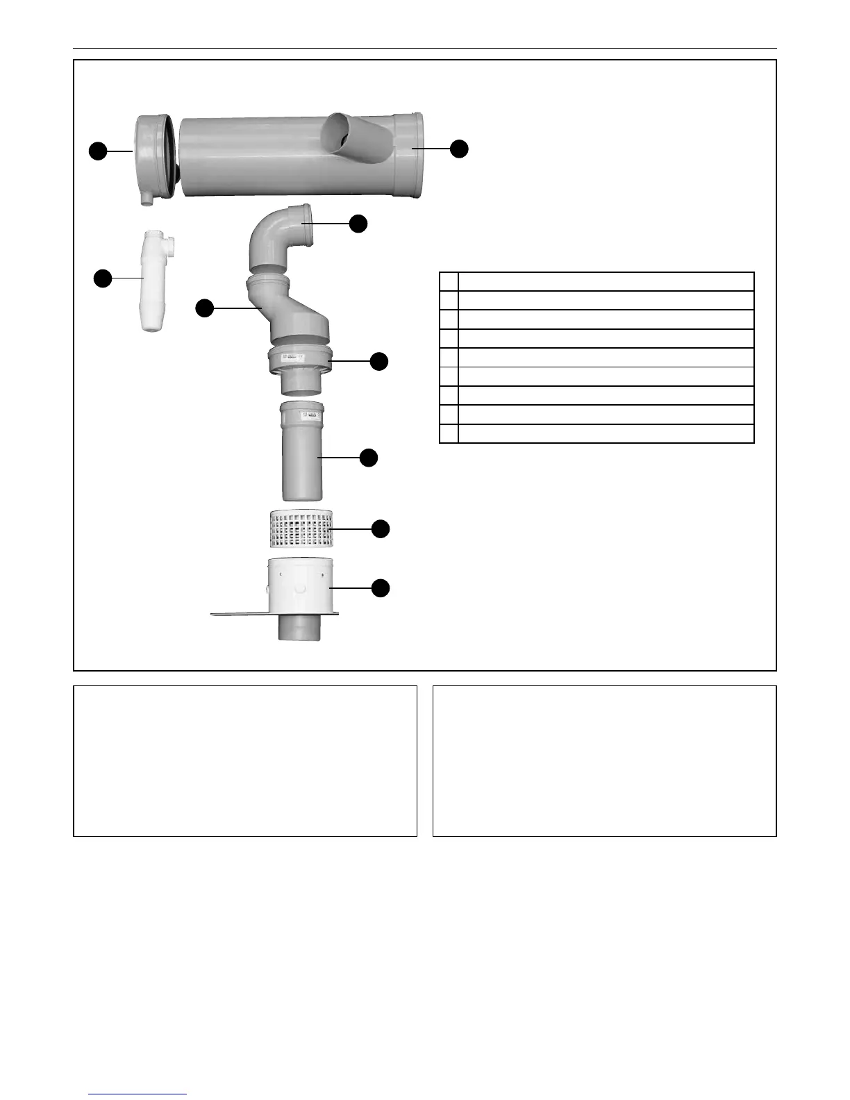
2.0 CASCADE FLUE COMPONENTS
(FIGURE 2.1)
4
EVOMAX - MULTILINE FLUE KITS
2
1
3
4
5
6
7
8
9
1 End Cap
2 Siphon
3 Collector Pipe (200 dia)
4 Elbow (90° x 100)
5 Non-Return Valve Connector (100 x 150)
6 Non-Return Valve Body (150 x 100 or 80)
7 Flue Extension Tube (100 or 80)
8 Air Intake Grill
9 Flue Connector (100/150 or 80/125)
The Cascade Flue system is supplied in two kits.
A Starter Kit & Extension Kit.
Wire retaining clips are also provided to prevent movement
of the tube connections by the inuence of expansion and
contraction. These must be tted to the ductwork to ensure
safe operation of the system.
2.2 STARTER KIT
This kit comprises all of the items shown in Figure 2.1.
There are two Kits available;
UIN 210264 for the 30-80 models
UIN 210268 for the 100-150 models
Drawings appended (p10 & p11)
2.3 EXTENSION KIT
This kit comprises the components required to t additional
single boilers to the system.
There are two Kits available;
UIN 210265 for the 30-80 models
UIN 210269 for the 100-150 models
Drawings appended (p12 & 13)
 Loading...