EVOMAX - MULTILINE FLUE KITS
6
FLUE DESIGN
!
3.0 FLUE DESIGN
3.01
The following standards are relevant to the
construction, installation & testing of ue systems.
BSEN 14471 Plastic Chimneys –
requirements and test methods
BSEN 1856-1 Metal Chimneys – Requirements
BSEN 1859 Metal Chimneys – Test methods
BS 6644 Installation & Maintenance
of gas red hot water
boilers 70kW – 1.8MW
3.0.2 The Flue Stack must be specied by a Flue Specialist
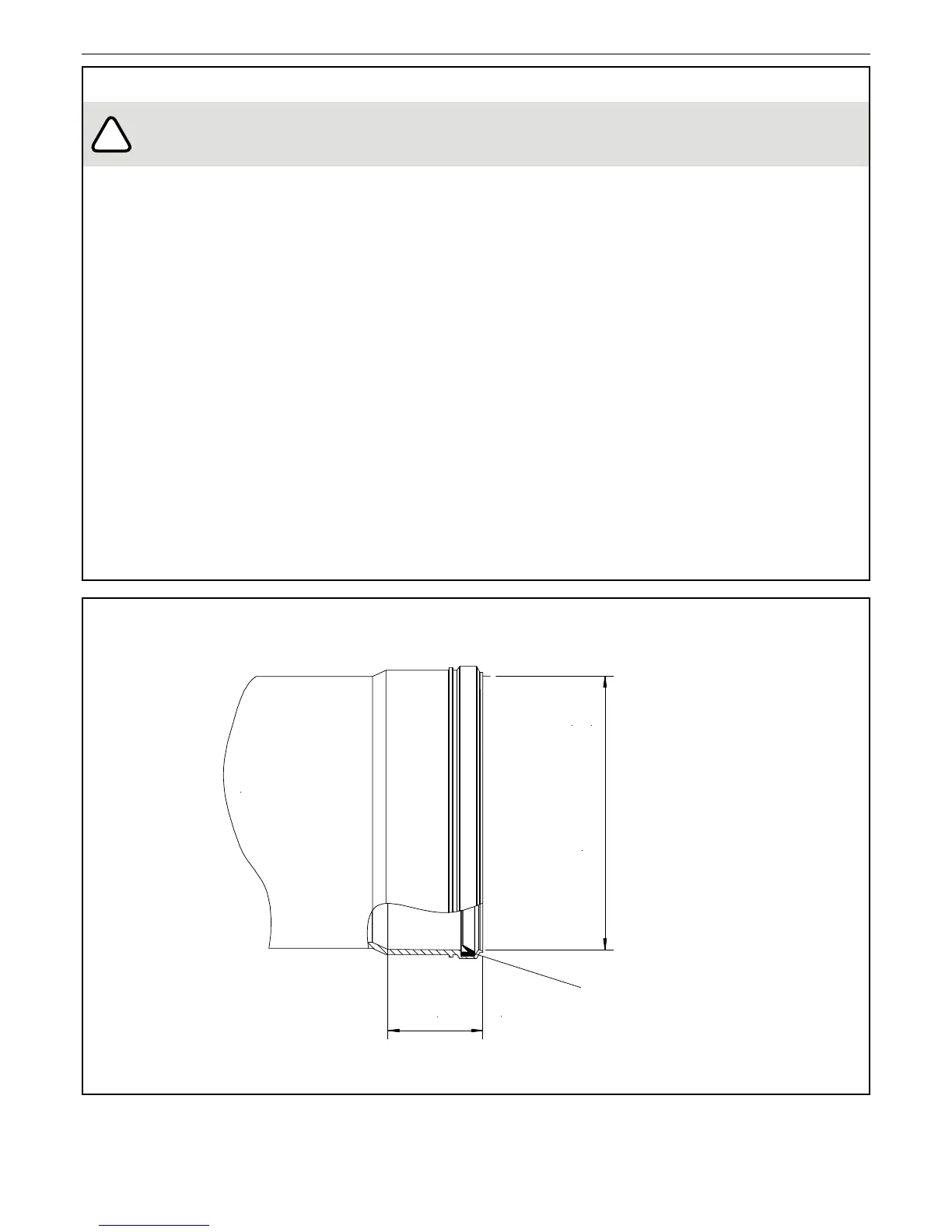
3.0.3 Design of the connecting ue spigot must refer to the
dimensions of the mating collar (Fig 3.1).
3.0.4 The Polypropylene header and EPDM seal are certied
to BSEN 14471.
3.0.5 Integrity of the ue joints and safety of operation must
be proven by the installer.
3.0.6 The ue resistance at ‘A’ in Figure 3.2 is not permitted to
exceed the maximum static pressure specication [Pmax]
quoted in Table 3.3 when operating at the maximum
capacity.
IMPORTANT: LEAKAGE OF FLUE PRODUCTS INTO THE ROOM WILL DEPLETE
THE OXYGEN LEVEL & INHIBIT SAFE COMBUSTION
.
3.0.7 The ue route should be planned to enable the least
directional change, one elbow is recommended as
depicted in Figure 3.2.
3.0.8 The ue pipe diameter must be at least 200mm, larger
diameters will permit longer ue length.
3.0.9 The ue material must be suitable for condensing
operation.
3.0.10 The terminal guard must prevent the ingress of objects
greater than 15mm diameter to comply with EN15502.
3.0.11 The Flue Terminal design should be selected to create the
least resistance and not compromise the potential ue
length. A wire mesh type is recommended with a
14mm grid.
3.0.12 Rain ingress may be ignored as the header design
enables excess water to be discharged through the
condensate drain.
FIGURE 3.1
(CASCADE HEADER INTERFACE DETAIL - FEMALE FLUE SOCKET CONNECTION)
 Loading...