EasyManuals Logo

IDEAL Evomax 120 Manual

IDEAL Evomax 120
16 pages
To Next Page IconTo Next Page
To Previous Page IconTo Previous Page
Page #7 background imageLoading...
Page #7 background image
EVOMAX - MULTILINE FLUE KITS 7
FLUE DESIGN
Evomax
Model Output
Cascade System Limits
Combustion Products
Data
Model
Maximum
System
Capacity
Maximum
Permissible
Header
Pressure
A’
(Static)
max
rate
CO
2
min
rate
CO
2
Temperature
Max
Max Min Hmax Pmax ± 0.5 ± 0.5
kW kW kW Pa % % C
30 7.5
400 40
9.7 9.0
72
40 10
60 15
80 20
100 25
600 80120 30
150 37.5
30P 7.5
400 40 11.4 10.6
40P 10
60P 15
80P 20
FIGURE 3.2
(FLUE SYSTEM LAYOUT)
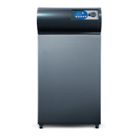
Customer specified components
'A'
'A'
At the maximum system
capacity the static pressure
generated against the ue
resistance at position [A]
must not exceed the value
Pmax quoted in Table 3.3.
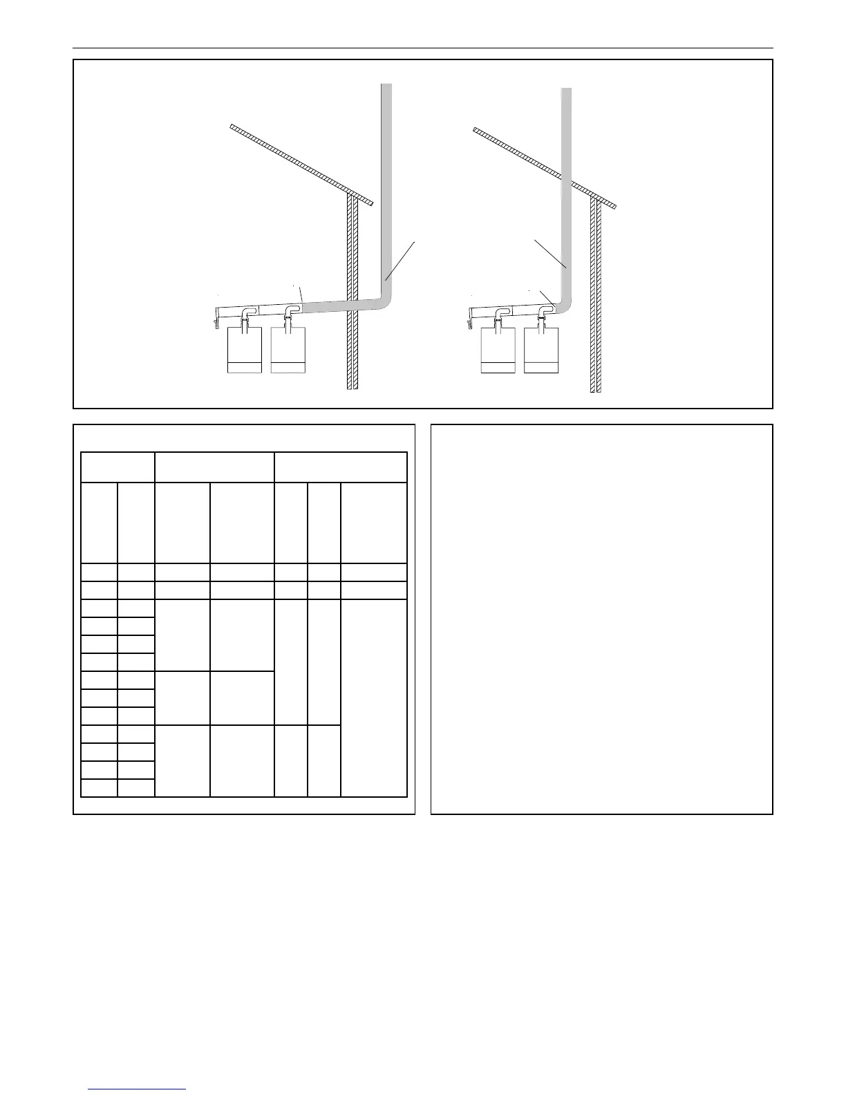
3.3 EVOMAX CASCADE FLUE SYSTEM DATA 3.4 DESIGN PROCEDURE
1. Determine the required total heat output. (Htot) [maximum
of 6 boilers per system].
2. Determine the required minimum heat output.
3. From Table 3.3 select the Evomax models required.
4. Using Figure 3.5 read the Combustion Products Flow Rate
(Qmax) at the Total System Capacity (Htot).
5. Record the information in Table 3.6
6. Calculate the maximum permissible ue length at
conditions Qmax & Pmax.
L = [a – (c + d)] / b (Table 3.6)

Other manuals for IDEAL Evomax 120

Questions and Answers:

Question and Answer IconNeed help?

Do you have a question about the IDEAL Evomax 120 and is the answer not in the manual?

IDEAL Evomax 120 Specifications

General IconGeneral
BrandIDEAL
ModelEvomax 120
CategoryBoiler
LanguageEnglish

Related product manuals