19
icos - Installation & Servicing
INSTALLATION
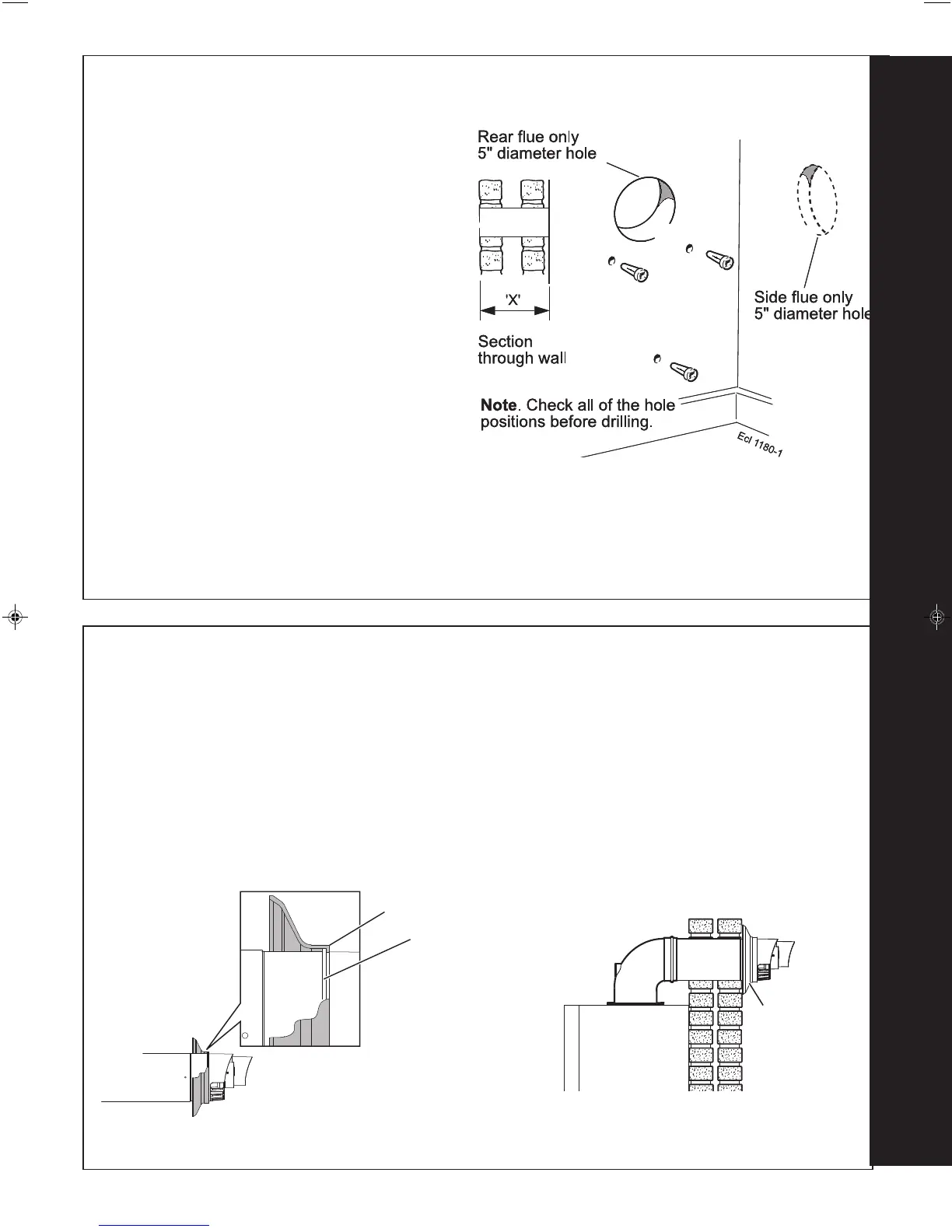
FLUE OUTLET
17
PREPARING THE WALL
IMPORTANT. Ensure that, during the cutting operation,
masonry falling outside of the building does not cause
damage or personal injury.
1. Cut the flue hole (preferably with a 5" core boring
tool), ensuring that the hole is square to the wall.
Both wall faces immediately around the cut hole
should be flat.
2. Drill 3 holes with a 7.5mm / 8mm masonry drill and
insert the plastic plugs provided, for the wall
mounting plate and the jacking screw plate.
Note.
If using the stand-off kit then drill 4 holes (choosing
one from each group but not the jacking screw).
3. Locate 2 No.14 x 50mm screws in the piping frame
(one at each side, in any of the 3 holes provided at
each side) and screw home.
Note.
If using the stand-off kit then locate the stand-off
channel and screw home.
18
TERMINAL WALL SEAL ASSEMBLY / POSITIONING
Ensure lip of wall seal is positioned
over step on plastic nose of flue terminal
(note, seal is cut away for clarity)
Step
isfu9783
Wall Seal Lip
Prior to fitting the flue, the rubber terminal wall seal provided
in the flue pack MUST be fitted to the flue terminal as shown
below in Figure 1.
FIGURE 1 FIGURE 2
Once the flue is installed it is IMPORTANT that the rubber
terminal wall seal is pressed against the outside wall to
create an adequate seal between the flue and wall as
shown in Figure 2.
var9784
Rubber
Terminal
Wall Seal

 Loading...