EasyManuals Logo

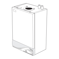
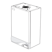
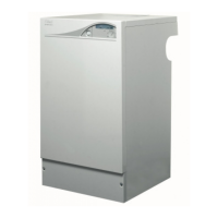
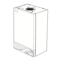
IDEAL icos HE12 User Manual

IDEAL icos HE12
60 pages
To Next Page IconTo Next Page
To Previous Page IconTo Previous Page
Page #14 background imageLoading...
Page #14 background image
14
icos - Installation & Servicing
INSTALLATION
nm8744b
40
94
40
8. Flue manifold.
10. Interpanel.
11. Burner assy.
12. Combustion chamber
Insulation.
13. Heat exchanger
14. Injector & housing
15. Venturi assy.
16. Fan assy.
17. Gas pipe assy.
19. Gas control valve assy.
20. Fan bracket assy.
21. Orifice plate.
22. Flue thermistor.
LEGEND
1. Front casing panel.
2. Sealing panel
3. Sump cover plate.
4. Bottom casing panel.
5. Flue sensing nipple.
6. Return pipe.
7. Flow pipe.
10
BOILER ASSEMBLY - Exploded view
23. Control thermistor.
24. Overheat thermostat.
25. Ignition electrode.
26. Flame detection electrode.
32. 'S' trap
33. Control assy.
40. Spark generator
44. Wall mounting plate.
53. Turret gasket kit.
94. Ignition lead
INSTALLATION

Questions and Answers:

Question and Answer IconNeed help?

Do you have a question about the IDEAL icos HE12 and is the answer not in the manual?

IDEAL icos HE12 Specifications

General IconGeneral
Modelicos HE12
CategoryBoiler
ManufacturerIDEAL
Output12 kW
Fuel TypeNatural Gas
MountingWall Mounted
ErP Heating EfficiencyA
Central Heating Flow Temperature Range30-80°C
Dimensions700 x 395 x 278 mm
Warranty2 years

Related product manuals