30
icos - Installation & Servicing
INSTALLATION
36
INTERNAL WIRING
Incoming mains wiring detail
A pictorial wiring diagram is shown in Frame 37.
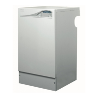
The mains lead connector is pre-fitted. This must be
removed to allow wiring.
1. Route the mains cable into the bottom LHS rear of the casing.
If using the stand-off kit then route through the grommet.
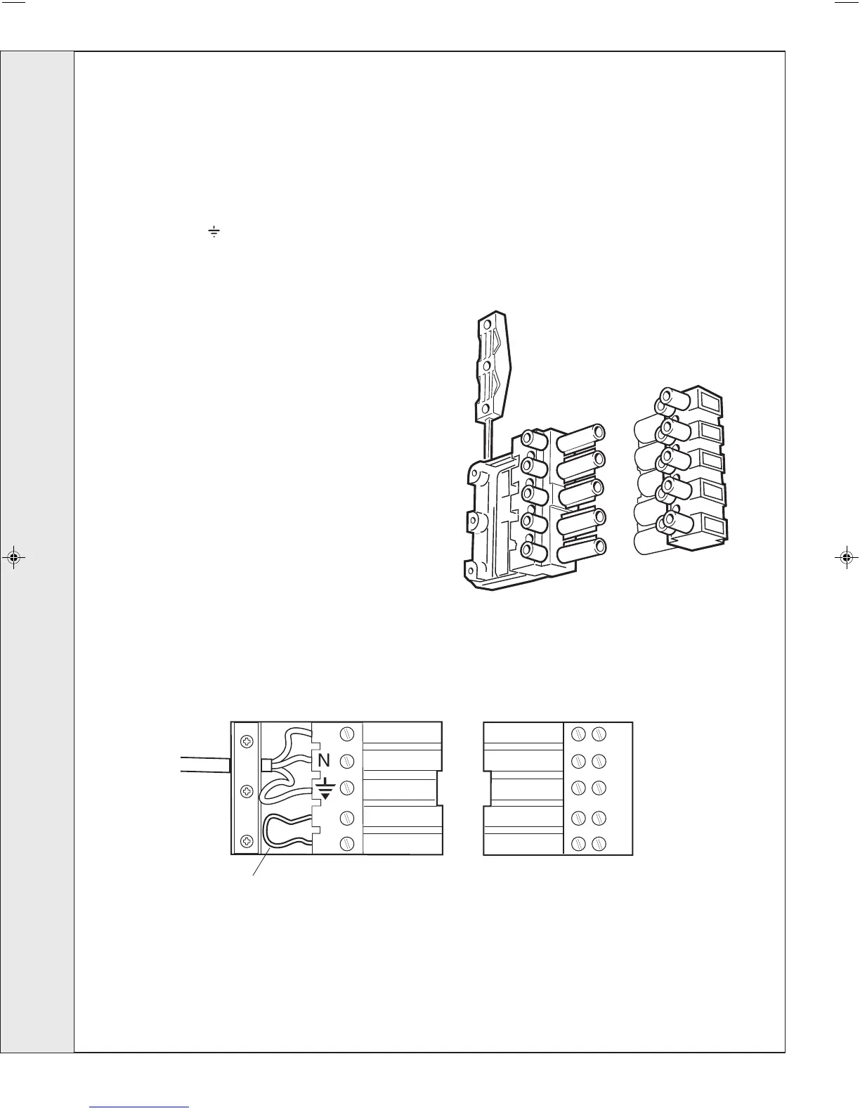
2. Wire a permanent live supply into the 5-way remote plug
terminals L3, N and
.
IMPORTANT. A permanent live is ESSENTIAL in order for
the advanced diagnostic controls to function correctly.
3. Wire the switched live supply into L2 or connect L1 and L2
via external control switching, as shown in Frame 32. In
either case, remove the wire link fitted L1 to L2.
4. Secure the mains lead with the cable clamp.
5. Connect the mains lead connector. Ensure it is fully located.
Note.
Ensure that the lengths of the current carrying conductors are
shorter than the earth conductor so that if the cable slips in its
anchorage the current carrying conductors become taut
before the earth conductor.
L1
Mains Connector
(supplied in hardware pack)
Socket
(fixed to boiler)
Remove link when connecting external programmer.
Ecl2367
INSTALLATION

 Loading...