5
4
4
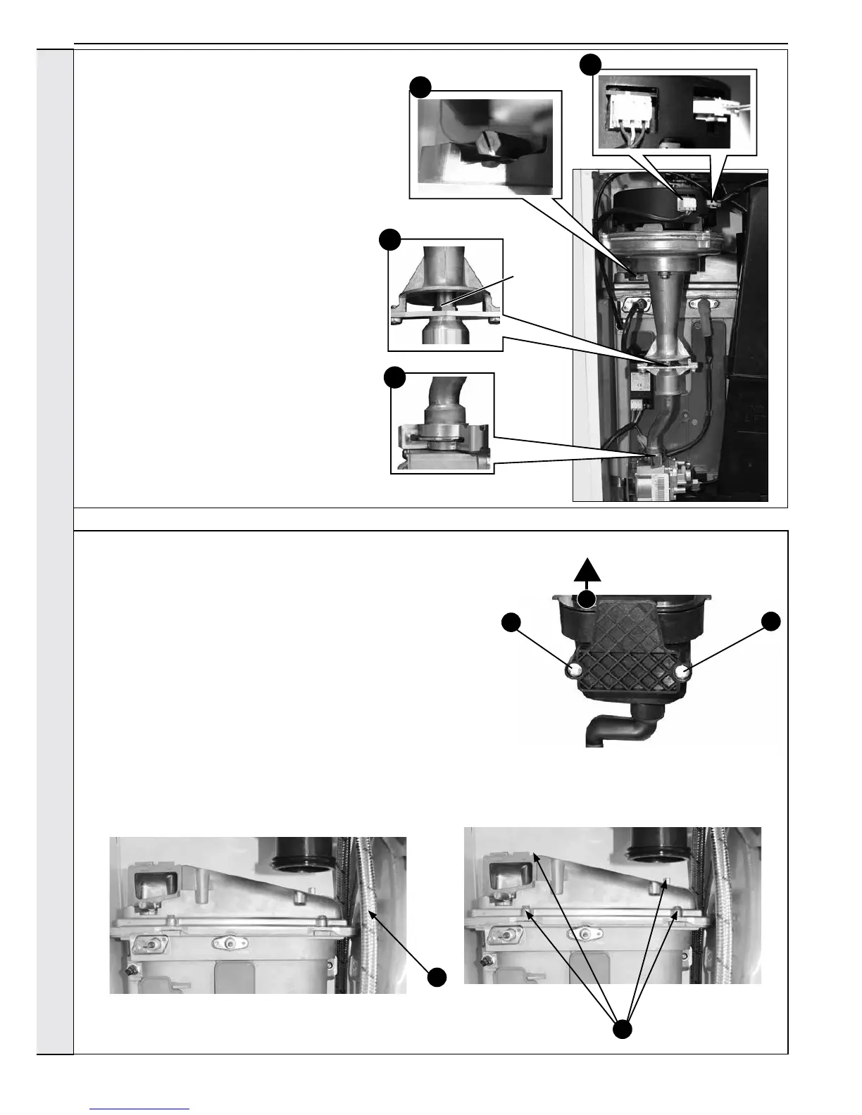
3.10 BURNER INJECTOR REPLACEMENT
1. Refer to Section 3.8.
2. Disconnect the electrical leads from the fan.
3. Remove the clip from the gas valve to
venturi pipe and ease the pipe upwards,
rotate and ease down to remove.
4. Loosen the screw retaining the fan
mounting bracket.
5. Lift and remove the fan and venturi
assembly.
6. Remove the 2 injector housing screws.
7. Withdraw the injector housing.
8. Fit the new injector housing complete with
injector.
9. Reassemble in reverse order, ensuring
that the new gas seal supplied is located
correctly in the injector housing.
10. Check operation of the boiler.
2
4
3.11 BURNER REPLACEMENT
1. See Section 3.8.
2. Refer to Section 3.4.
3. Remove the fan. Refer to Section 3.9.
4. Undo the two screws and remove the sump cover.
5. Lift the manifold to clear the bottom sealing gasket and remove manifold.
6. Remove the 2 front xing screws and remove the 2 rear extended nuts.
7. Lift off the burner from the combustion chamber. To facilitate the
removal, hold the DHW exible pipe against the front of the expansion
vessel while withdrawing the burner.
8. Fit the new burner, replacing any damaged or deteriorating sealing
gasket.
9. Reassemble in reverse order. Refer to Section 3.7.
10.
Check the operation of the boiler. Refer to Sections 2.22 & 2.23.
7
6
3
6
Injector
SERVICING