EasyManuals Logo
Home>IDEAL>Boiler>Logic HEAT 12

IDEAL Logic HEAT 12 Installation And Servicing

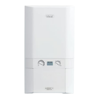
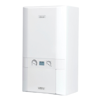
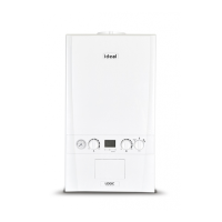
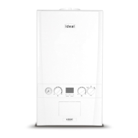
IDEAL Logic HEAT 12
72 pages
To Next Page IconTo Next Page
To Previous Page IconTo Previous Page
Page #34 background imageLoading...
Page #34 background image
34
INSTALLATION
Ideal Logic Heat - Installation and Servicing
38
WIRING DIAGRAM
1
X1A
X1BX1CX1DX2AX2BX3X7AX7B
X5X6X8
2123
sLENL ENL
123123412341235 41231212
1234123456123456789
1011
Fan
Return
Thermistor
Control
Thermistor
Flame
Sensor
Electrode
Spark
Electrode
Spark
Generator
PCB
Gas
Valve
Chassis
Earth
Service
Connector
Fused
at 4AT
Mains
Switched Live
Water
Flow
Sensor
r
b
br
br
br
br
p
p
yb
b
b
b
bb
bk
bk
bk
bk
bk
bk
bk
bk
bk
r
y/g
y/g
y/g
y/g
y/g
y/g
y/g
r
bk
b
y
p
y/g
br
KEY
- red
- black
- blue
- yellow
- pink
- yellow/green
- brown
INSTALLATION

Other manuals for IDEAL Logic HEAT 12

Questions and Answers:

Question and Answer IconNeed help?

Do you have a question about the IDEAL Logic HEAT 12 and is the answer not in the manual?

IDEAL Logic HEAT 12 Specifications

General IconGeneral
BrandIDEAL
ModelLogic HEAT 12
CategoryBoiler
LanguageEnglish

Related product manuals